Leisure vehicle

a technology for vehicles and sports, applied in the field of sports vehicles, can solve the problems of difficult to start or accelerate the vehicle, and achieve the difficulty of smooth start or smooth acceleration

Active Publication Date: 2006-12-07
KAWASAKI MOTORS LTD
View PDF3 Cites 16 Cited by
  • Summary
  • Abstract
  • Description
  • Claims
  • Application Information

AI Technical Summary

Benefits of technology

[0003] The present invention addresses the above described conditions, and an object of the present invention is to provide a leisure vehicle capable of a smooth start or smooth acceleration on sandy soil, a snowy road and so on, where a grip force between a wheel thereof and a ground surface is small.

Problems solved by technology

Since a grip force between the wheels and a ground surface of the sandy soil is small, it is in many cases difficult to start or accelerate the vehicle without occurrence of a substantial slip.
If a large drive force (rotational torque) is applied to a drive wheel during a start or during acceleration, the drive wheel tends to slip, making it difficult to achieve a smooth start or smooth acceleration.

Method used


Image

  • Leisure vehicle
  • Leisure vehicle
  • Leisure vehicle

Examples


embodiment 1

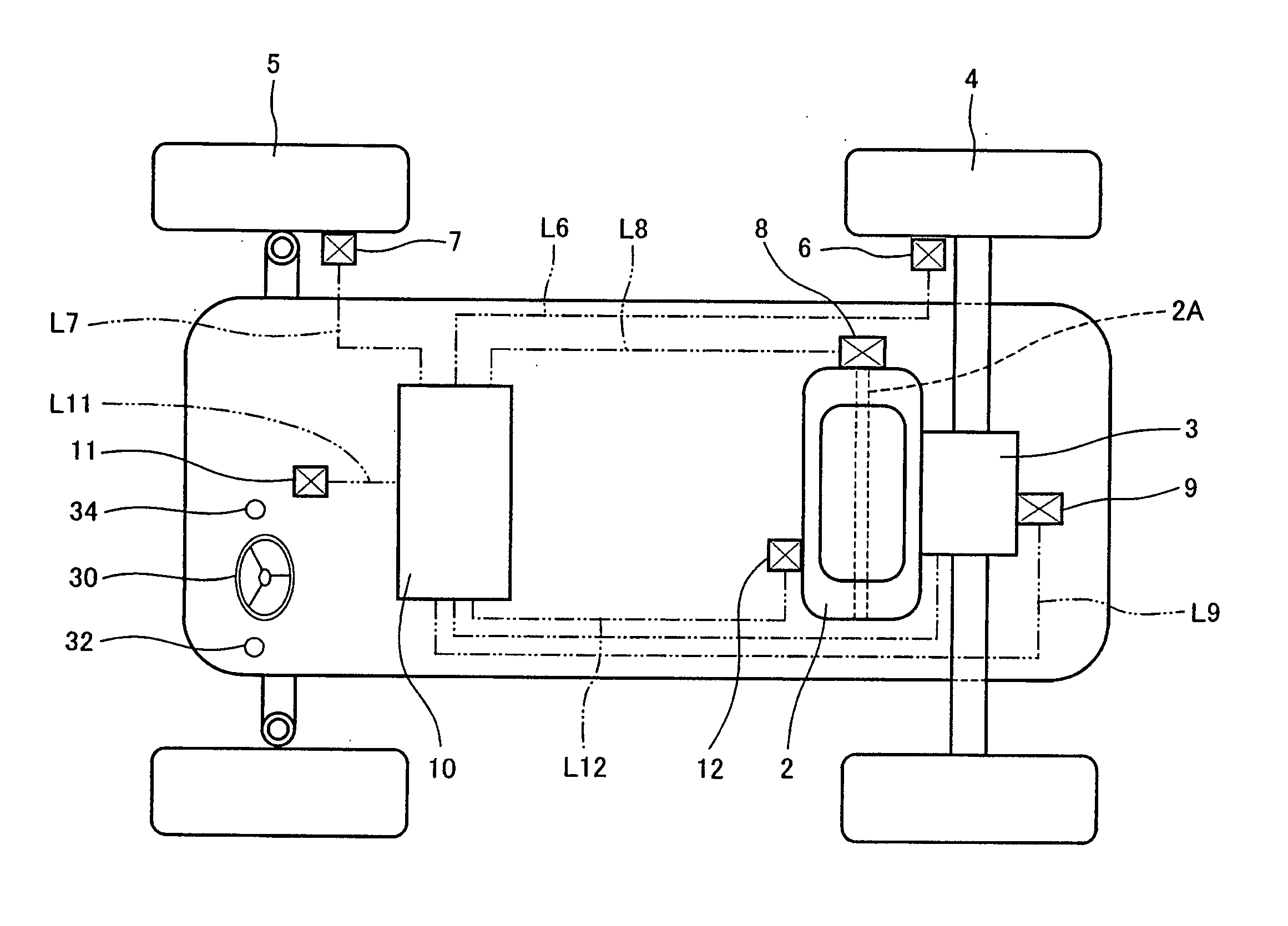
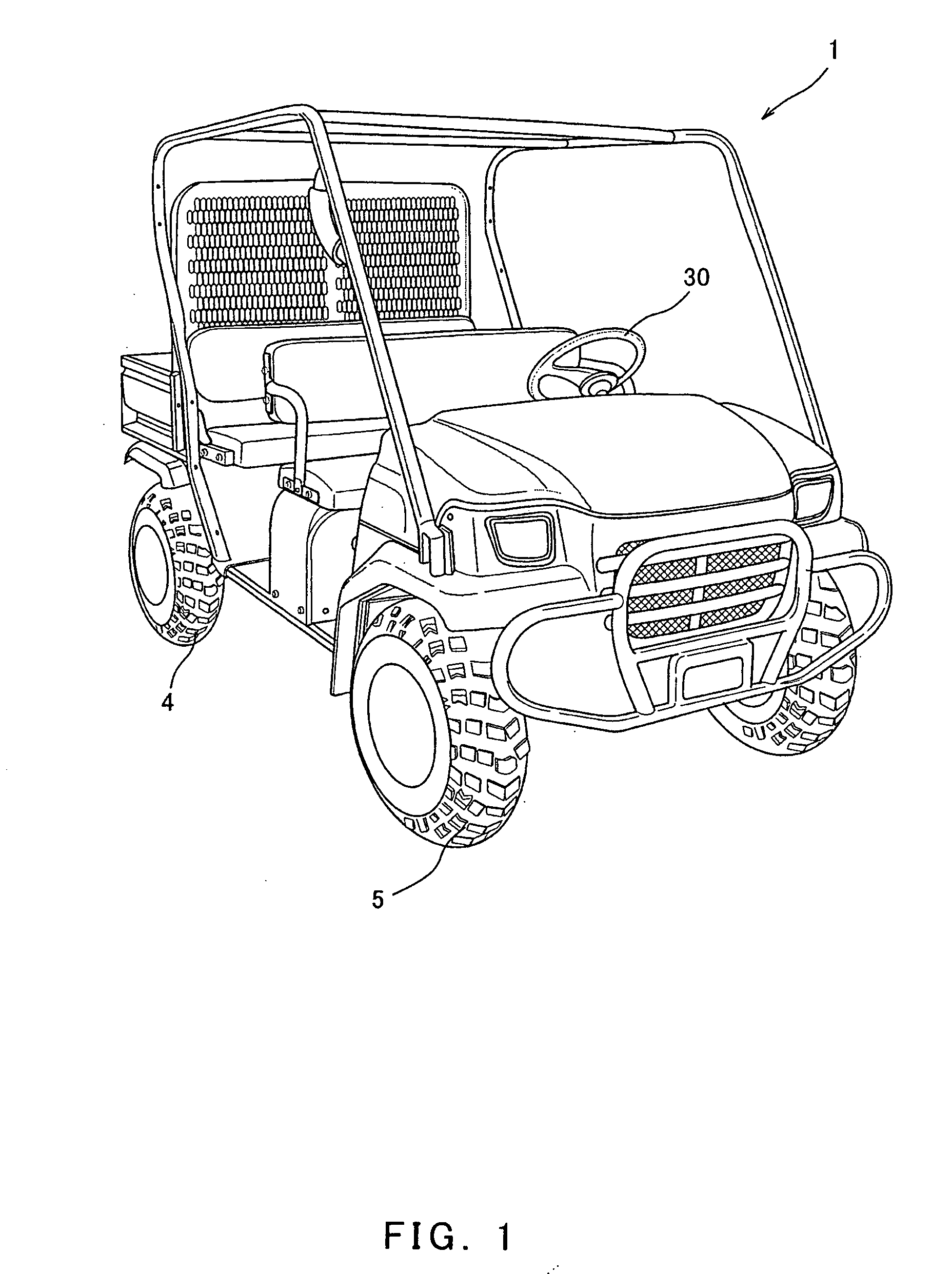
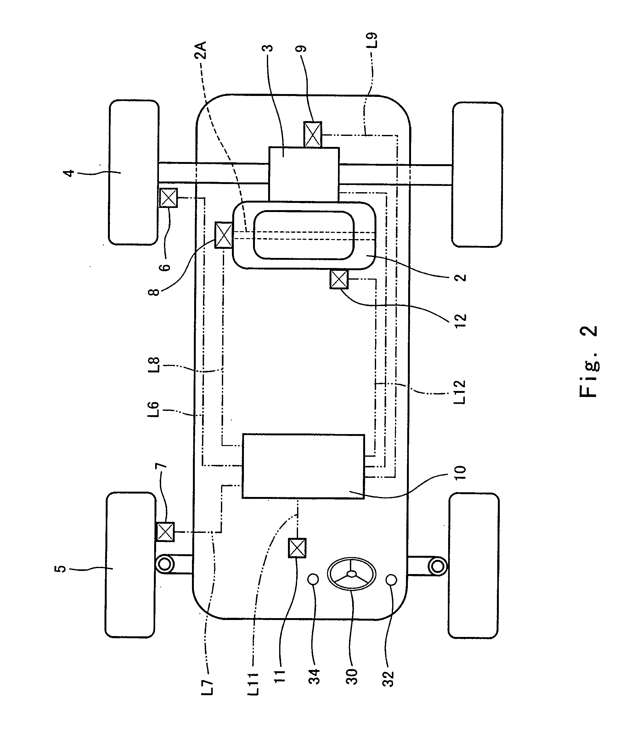
[0026] Turning now to FIG. 1, a utility vehicle 1, which is one type of a leisure vehicle used for loading and unloading in farms or ranches, is shown. Turning to FIG. 1 or 2, a drive force from an internal combustion engine (hereinafter simply referred to as an engine) 2, which is a power unit, is transmitted to rear wheels 4 which are drive wheels. The drive force is transmitted through a transmission 3 to drive the rear wheels 4, enabling the utility vehicle 1 to drive. The transmission 3 has a plurality of gear positions. A steering handle 30 is mounted in a driver's seat section and is rotated clockwise or counterclockwise within a predetermined angular range to steer front wheels 5 which are non-drive wheels (free wheels) to change a running direction freely.

[0027] A drive wheel rotational speed sensor unit 6 is attached to the rear wheel 4 and is configured to detect a rotational speed of the rear wheel 4. A non-drive wheel rotational speed sensor unit 7 is attached to the f...

embodiment 2

[0048] In a second embodiment, the controller 10 detects the rotational speed of the front wheel 5 which is the non-drive wheel and the rotational speed of the rear wheel 4 which is the drive wheel from the non-drive wheel rotational speed sensor unit 7 and the drive wheel rotational speed sensor unit 6, respectively, and increases the engine speed at a predetermined rate, for example, 20 revolutions per second when a ratio of the rotational speed of the rear wheel 4 to the rotational speed of the front wheel 5 (rotational speed of the rear wheel 4 / rotational speed of the front wheel 5) is smaller than a predetermined value, for example, 1.05. On the other hand, when the ratio of the rotational speed is the predetermined value or larger, for example, 1.05 or larger, the controller 10 determines that the rear wheel 4 has slipped in a predetermined amount or more, and decreases the engine speed so that the ratio of the rotational speed of the rear wheel 4 to the rotational speed of th...

embodiment 3

[0049] The controller 10 may increase or decrease the engine speed so as to correspond to the ratio of the rotational speed between the rear wheel (drive wheel) 4 and the front wheel (non-drive wheel) 5. Specifically, for example, the controller 10 may increase the engine speed at a rate of 20 revolutions per second when the ratio is 1.0, increase the engine speed at a rate of 10 revolutions per second when the ratio is not smaller than 1.0 and smaller than 1.005, and increase the engine speed at a rate of 5 revolution per second when the ratio is not smaller than 1.005 and smaller than 1.02. Furthermore, the controller 10 may maintain the engine speed of the engine 2 at that point of time when the ratio is not smaller than 1.02 and smaller than 1.03 and decrease the engine speed so that the ratio of the rotational speed becomes a value that is not smaller than 1.02 and smaller than 1.03, when the ratio is not smaller than 1.03. These numeric values are merely exemplary and may be s...


PUM


Abstract

A leisure vehicle configured to be propelled by a friction between a drive wheel thereof and a ground surface with which the drive wheel is in contact, including a power unit configured to drive the drive wheel, a speed control device configured to control drive of the drive wheel, and a controller configured to control the speed control device to increase a rotational speed of the drive wheel while maintaining a state in which the drive wheel does not slip on the ground surface in a predetermined amount or more.

Description

TECHNICAL FIELD [0001] The present invention relates to a leisure vehicle such as a motorcycle, an ATV (all terrain vehicle), or a utility vehicle which is configured to run on the ground with wheels. BACKGROUND ART [0002] A leisure vehicle, for example, an ATV, typically runs with wheels on the ground through various conditions, such as sandy soil. In such cases, the ATV is more likely to start and accelerate on the sandy soil. Since a grip force between the wheels and a ground surface of the sandy soil is small, it is in many cases difficult to start or accelerate the vehicle without occurrence of a substantial slip. If a large drive force (rotational torque) is applied to a drive wheel during a start or during acceleration, the drive wheel tends to slip, making it difficult to achieve a smooth start or smooth acceleration. In such situations, a driver of the vehicle is required to manipulate an accelerator of the vehicle to cause a power unit such as an engine to drive the wheel ...

Claims


Application Information

Patent Timeline
Patent Type & Authority Applications(United States)
IPC IPC(8): B60K28/16B60W10/02B60W10/04B60W10/06B60W30/02F02D29/02
CPCB60W2520/26B60Y2200/114B62M7/00B62J27/00B60Y2200/86
Inventor MATSUDA, YOSHIMOTO
Owner KAWASAKI MOTORS LTD
Why Eureka
Try Eureka