
Stirling Engine for Vehicles

a stirling engine and vehicle technology, applied in the field of stirling engines, can solve the problems of large driving power, rapid decrease rapid increase of temperature of operation fluid in the heating portion, so as to reduce vehicle speed, increase the temperature of the heat accumulator, and reduce the driving power

Inactive Publication Date: 2009-11-05
ISUZU MOTORS LTD
View PDF8 Cites 6 Cited by
  • Summary
  • Abstract
  • Description
  • Claims
  • Application Information

AI Technical Summary

Benefits of technology

[0010]When the brake of the vehicle is being applied, the Stirling engine of the present invention for driving the vehicle is changed by the operating condition-changing device over to the heat pump operation. That is, when the brake is being applied, the Stirling engine that had been producing the power using the heat from the heating portion in the normal traveling is caused to work as the heat pump through the power transmission system of the vehicle. When the brake is applied, the kinetic energy of the vehicle is consumed within a short period of time and the vehicle speed decreases. Therefore, a very large driving power is produced when the Stirling engine is operated as the heat pump, whereby the temperature of the operation fluid quickly decreases in the cooling portion and the temperature of the operation fluid quickly increases in the heating portion. Heat accumulators are arranged in the heating portion and in the cooling portion of the Stirling engine. The heat pump operation at the time braking is accompanied by an increase in the temperature in the heat accumulator of the heating portion and a decrease in the temperature in the heat accumulator of the cooling portion. As a result, the kinetic energy of the vehicle is regenerated as the temperature differential energy being accumulated in the heat accumulators.
[0011]At the time of accelerating the vehicle again after having applied the brake, the Stirling engine is operated as the engine to drive the vehicle by utilizing the temperature differential energy accumulated in the heat accumulators of the heating portion and the cooling portion. At this moment, the temperature of the heating portion has been elevated to be higher than the temperature in the normal state and the temperature of the cooling portion has been lowered. Therefore, the Stirling engine operates in a state of an increased temperature difference between the high heat source and the low heat source, producing an increased output to smoothly accelerate the vehicle. Further, the amount of fuel fed to the heating portion can be greatly decreased contributing to improving the fuel economy.
[0012]When traveling the downhill, too, the Stirling engine is changed over to the heat pump operation by the operating condition-changing device. The power required for driving the Stirling engine as the heat pump is very larger than the power which the Stirling engine absorbs when it simply operates as the engine brake. Therefore, a strong braking force acts on the vehicle. Namely, the Stirling engine can be operated as the so-called deceleration device (retarder) decreasing the burden on the foot brake when traveling the downhill. This effect becomes conspicuous particularly with a large and heavy vehicle such as a truck or the like preventing the fading phenomenon that is caused by the overheated braking device. The energy that is regenerated while the heat pump is in operation is transformed into the temperature differential energy, is accumulated in the heat accumulators, and is utilized for the subsequent traveling in the same manner as the one of when applying the brake described above.

Problems solved by technology

Therefore, a very large driving power is produced when the Stirling engine is operated as the heat pump, whereby the temperature of the operation fluid quickly decreases in the cooling portion and the temperature of the operation fluid quickly increases in the heating portion.

Method used


Image

  • Stirling Engine for Vehicles
  • Stirling Engine for Vehicles
  • Stirling Engine for Vehicles

Examples


Embodiment Construction

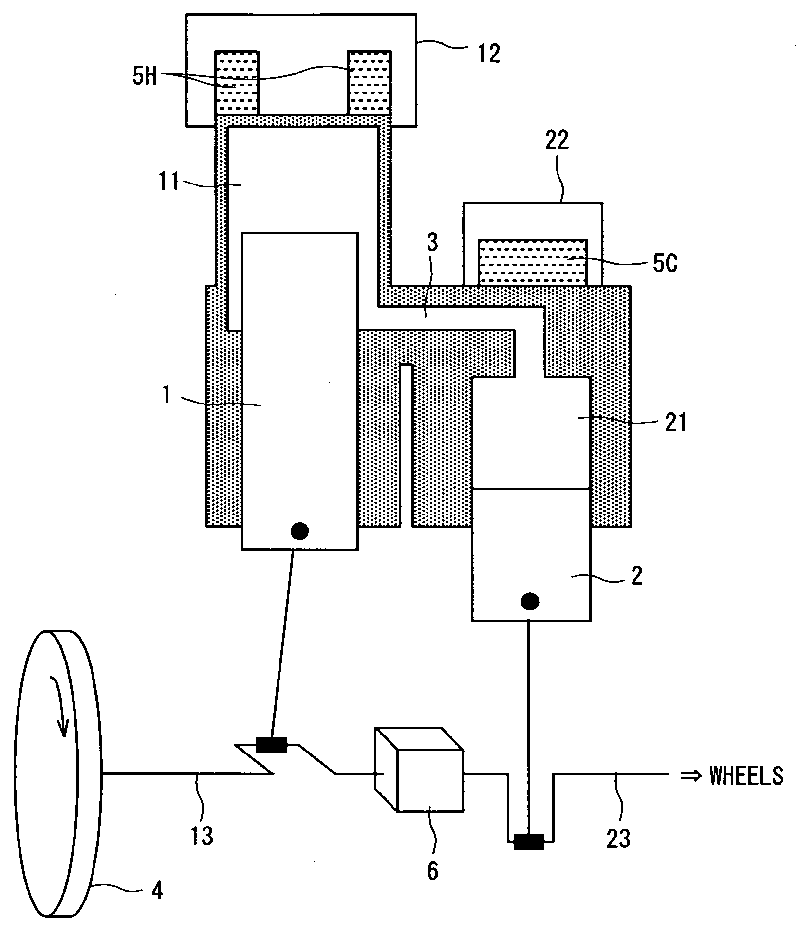
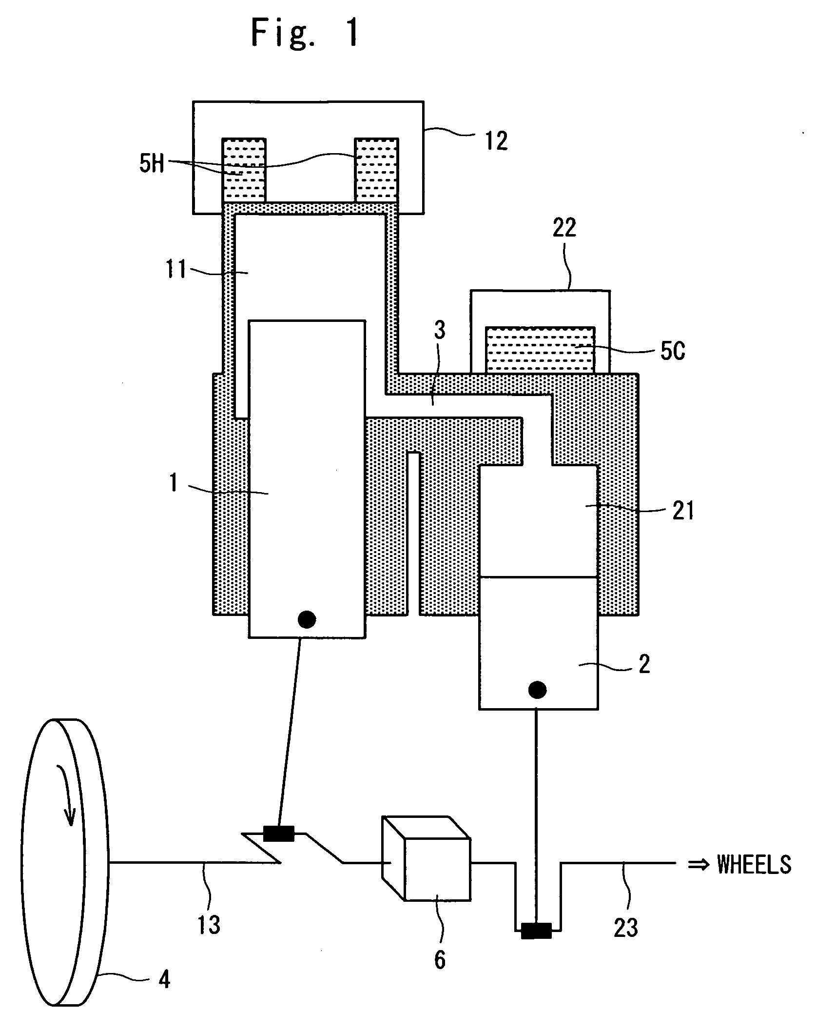
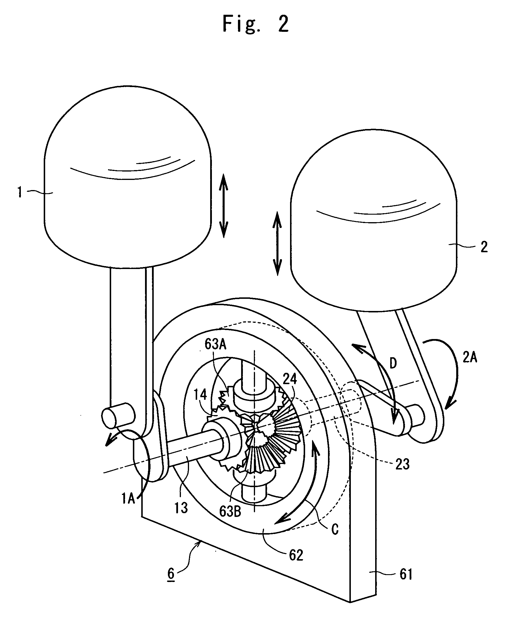
[0021]The Stirling engine of the invention will now be described with reference to the drawings. FIG. 1 is a schematic diagram illustrating a first embodiment of the Stirling engine of the invention and FIG. 2 is a view illustrating a phase difference-changing mechanism which is an operating condition-changing device of the Stirling engine of FIG. 1. Further, FIG. 3 is a schematic diagram of a control system for changing the operating condition of the Stirling engine of FIG. 1 and FIG. 4 is a graph illustrating a relationship between the output and the phase of the Stirling engine.

[0022]The Stirling engine of the embodiment of FIG. 1 is of the type of an engine equipped with two cylinder / piston mechanisms arranged in parallel, the piston 1 serving as a piston on the expansion side and the piston 2 serving as a piston of the compression side. The cylinder space in the upper part of the piston 1 is a heating space 11, and the cylinder space in the upper part of the piston 2 is a cooli...


PUM


Abstract

A Stirling engine mounted on a vehicle to efficiently absorb and accumulate the kinetic energy of the vehicle at the time of braking, to improve fuel economy during traveling of the vehicle and to increase the braking effect of an engine brake. The Stirling engine for driving the vehicle is provided with an operating condition-changing device which, at the time of braking the vehicle, changes the operating condition of the Stirling engine over to the heat pump operation. The Stirling engine having, for example, two pistons is provided with the phase difference-changing mechanism 6 for changing a relative phase of the piston 1 and the piston 2. When the brake is applied, the phases of the two pistons are changed to effect the heat pump operation using the power from drive wheels of the vehicle. Heat accumulators 5H and 5C are installed in a heating portion 12 and a cooling portion 22 of the Stirling engine. Braking the vehicle regenerates kinetic energy in heat accumulators as a temperature differential energy which is utilized for the subsequent traveling.

Description

TECHNICAL FIELD[0001]This invention relates to a heat engine or a so-called Stirling engine which transforms the heat energy possessed by a heat source into the mechanical rotational energy by utilizing an operation fluid sealed in a gaseous state which changes depending upon the heating and cooling. More particularly, the present invention relates to a Stirling engine mounted on a vehicle.BACKGROUND ART[0002]The Stirling engine is an external combustion engine having a high theoretical heat efficiency which periodically heats and cools the operation fluid sealed in an operation chamber to change the state, and takes out the rotational energy from a high heat source by utilizing the change in the state. In an internal combustion engine such as a gasoline engine or a diesel engine, a fuel is intermittently burned in the air which is an operation fluid. In the Stirling engine which is an external combustion engine, unlike an internal combustion engine, heat produced by the continuous ...

Claims


Application Information

Patent Timeline
Patent Type & Authority Applications(United States)
IPC IPC(8): F02G1/04
CPCF02G1/045F02G2280/70F02G2280/60F02G1/053
Inventor ABE, MAKOTOYAMAMOTO, YASUSHI
Owner ISUZU MOTORS LTD
Learn More