
Vehicle Power Transmission Device Using A Fluid Coupling

Inactive Publication Date: 2007-09-06
ISUZU MOTORS LTD
View PDF8 Cites 6 Cited by
  • Summary
  • Abstract
  • Description
  • Claims
  • Application Information

AI Technical Summary

Benefits of technology

[0024] That is, the turbo charger reaches a steadily operating condition after the passage of a period of operation lag, the operating condition being determined by the engine operating conditions such as the amount of depressing the accelerator pedal. Usually, the driver, at the start, greatly depresses the accelerator pedal. After the passage of the period of operation lag, therefore, the turbo charger reaches a high output state close to the operating condition of when the engine is in full-load operation. Therefore, the engine produces a large output, and the output torque and the revolution increase. In the present invention, however, the lockup clutch is not connected at this moment. Therefore, no extended period of time is required for connecting the lockup clutch and, besides, the shock at the time of connecting is suppressed. When the boost is elevated due to a large turbo charger output and the engine produces a large output, connecting of the lockup clutch is completed and the engine is directly coupled to the transmission. Therefore, the vehicle accelerates smoothly accompanying an increase in the engine output.
[0027] As described in claim 4, the lockup clutch can be connected more reliably when the vehicle speed is detected by the lockup clutch control device and when connecting the lockup clutch is controlled depending upon the vehicle speed. Besides, the power transmission device that uses the fluid coupling is suited, by its own nature, for a diesel engine. As described in claim 4, therefore, the present invention can be effectively applied to a diesel engine.

Problems solved by technology

So far as the fluid coupling 2 involves slipping, however, the power transmission efficiency never reaches 100% and the diesel engine consumes the fuel wastefully.
At the start of the engine or during the low-load operation where the amount of the exhaust gas is small, therefore, its revolution is so low that its function is not exhibited to a sufficient degree.
When the fluid coupling with the lockup clutch is coupled to the turbo engine, however, it became clear that there arouses a problem concerning the timing for connecting the lockup clutch after the start of the vehicle.

Method used


Image

  • Vehicle Power Transmission Device Using A Fluid Coupling
  • Vehicle Power Transmission Device Using A Fluid Coupling
  • Vehicle Power Transmission Device Using A Fluid Coupling

Examples


Embodiment Construction

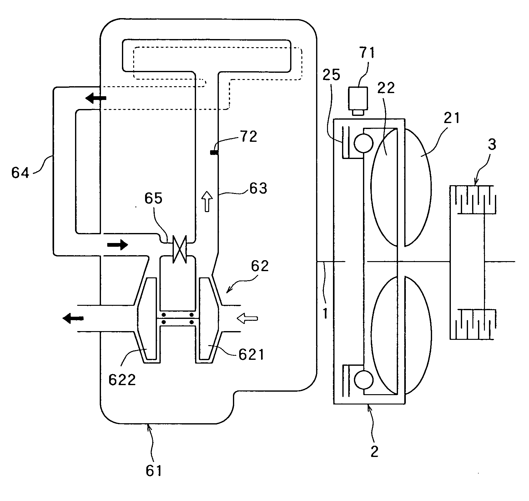
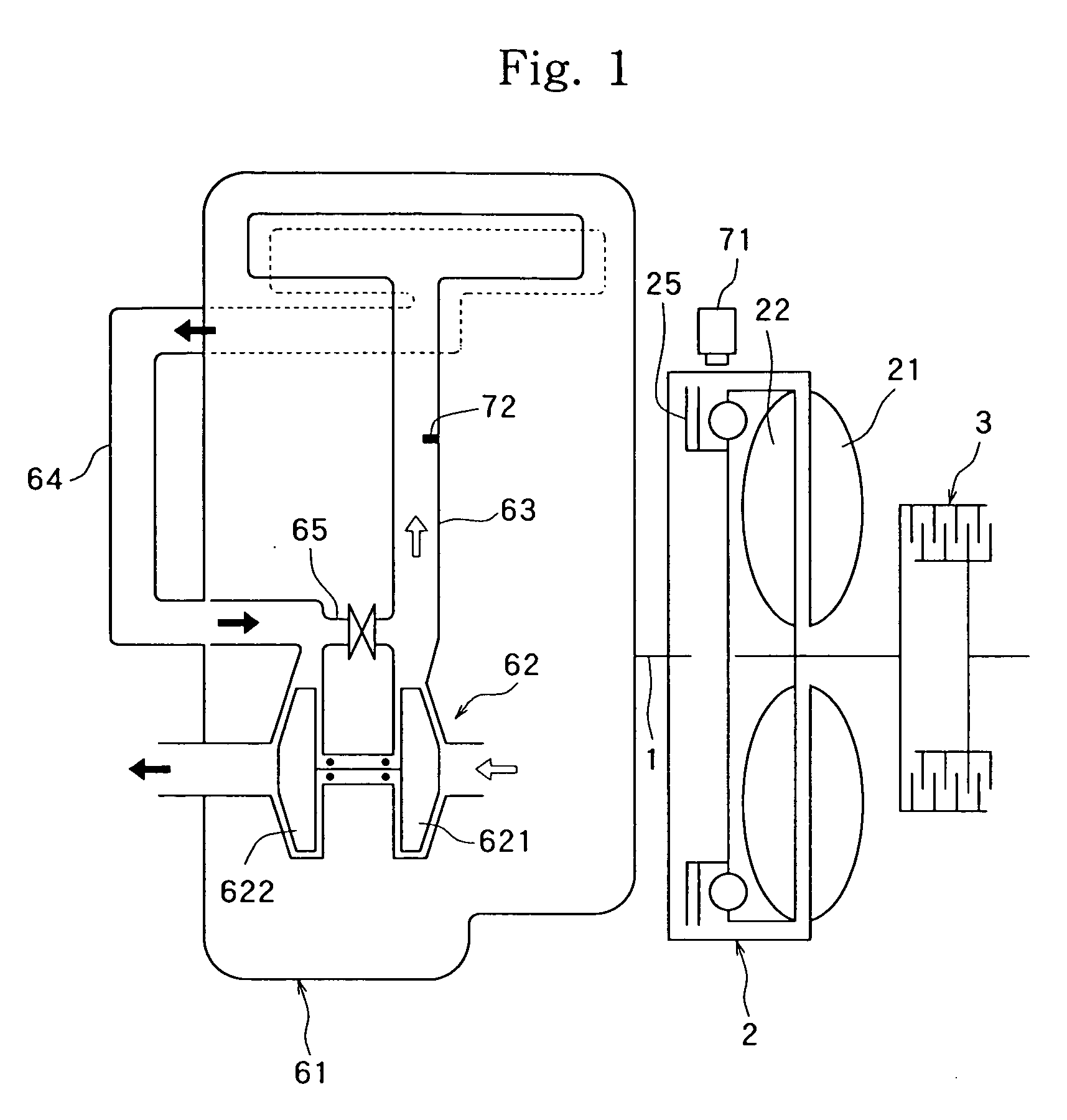
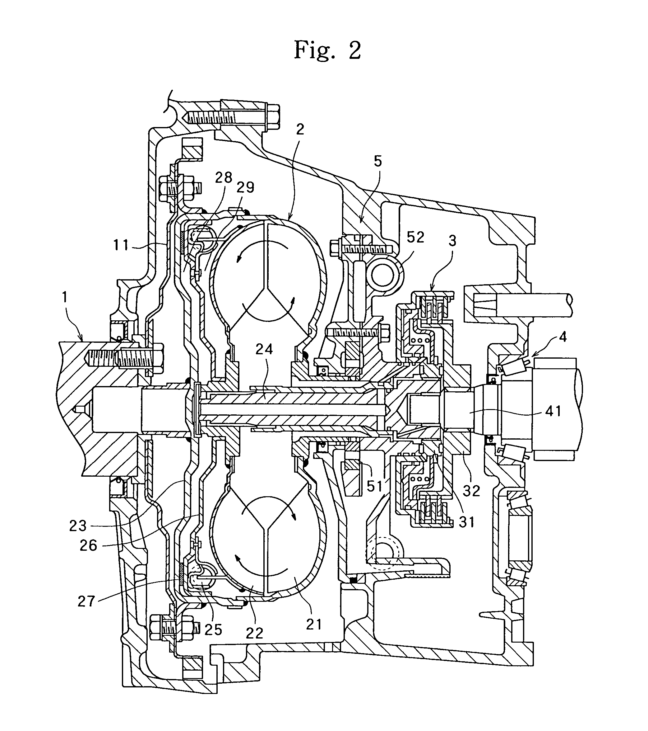
[0037] Described below with reference to the drawings is a vehicle power transmission device with a fluid coupling embodying the present invention. FIG. 1 schematically illustrates a vehicle power transmission device of the present invention including a diesel engine 61. The diesel engine 61 is equipped with a turbo charger 62 for charging. The turbo charger 62 includes a compressor 621 for compressing the air that is fed to the engine cylinders, and a compressor-driven turbine 622 coupled thereto. The air compressed by the compressor 621 has a pressure (boost) that is elevated, and is fed into the cylinders through the intake pipe 63. The exhaust gas after burned in the cylinder flows into the compressor-driven turbine 622 through the exhaust pipe 64 to drive it. The diesel engine is provided with an EGR passage 65 for recirculating the exhaust gas into the intake pipe 63 in order to decrease NOx in the exhaust gas.

[0038] The power of the diesel engine 61 is transmitted from the c...


PUM


Abstract

A vehicle power transmission device in which an engine 61 equipped with a turbo charger 62 and a fluid coupling 2 with a lockup clutch are combined together, wherein a timing for connecting the lockup clutch 25 is normalized to accomplish a smooth connecting during the low-speed traveling after the start. A lockup clutch control device is equipped with means for detecting the operating condition of the turbo charger 62, and the lockup clutch 25 starts to be connected at a moment before the turbo charger 62 reaches a high output state. The lockup clutch 25 is connected within a short period of time without producing a shock due to connection and the vehicle, thereafter, accelerates smoothly. A rate of change in the revolution of the engine 61 or the pressure in the intake pipe 63 is detected to detect the operating condition of the turbo charger 62.

Description

TECHNICAL FIELD [0001] The present invention relates to a vehicle power transmission device which includes a fluid coupling between an engine and a transmission, making it possible to accomplish a smooth start by utilizing the slipping between the pump and the turbine in the fluid coupling at the time of starting the vehicle without requiring cumbersome clutch operation by the driver of a vehicle. BACKGROUND ART [0002] A variety kinds of vehicle power transmission devices for easy driving have been developed in an attempt to facilitate the driving of vehicles and to reduce fatigue to the drivers by automatically operating the clutch or the transmission that transmits the power of the engine to the wheels. [0003] A representative example may be a so-called AT vehicle by using a power transmission device comprising a torque converter which is a fluid transmission device and a planetary gear mechanism. One of them may be a power transmission device for easy drive which uses a transmiss...

Claims


Application Information

Patent Timeline
IPC IPC(8): F02D23/00F16H61/14
CPCY10T477/50F16H61/143
Inventor IWAO, NOBUYUKIYAMAMOTO, YASUSHIYAMAZAKI, ATSUSHIKUWATA, TAKAHIRO
Owner ISUZU MOTORS LTD
Learn More