
Variable resolution single lever speed control for a hydrostatic transmission

a technology of hydrostatic transmission and variable resolution, which is applied in the direction of motor/generator/converter stopper, gearing, dynamo-electric converter control, etc., can solve the problems that the propelling speed of the machine cannot always be controlled as sensitively as desired, and the machine has to stop, etc., to achieve smooth acceleration of the machine, small slope, and optimal resolution

Active Publication Date: 2008-08-26
DEERE & CO
View PDF7 Cites 4 Cited by
  • Summary
  • Abstract
  • Description
  • Claims
  • Application Information

AI Technical Summary

Benefits of technology

[0006]It is an advantage of the invention that the range of movement or stroke of the desired speed input means is always adjusted to the actual drive situation. Thus, a sufficiently sensitive speed input means having an optimal resolution is provided. The operator does not need to operate any switches to determine or adjust the relation between the desired speed and the propelling speed to the actual operation situation.
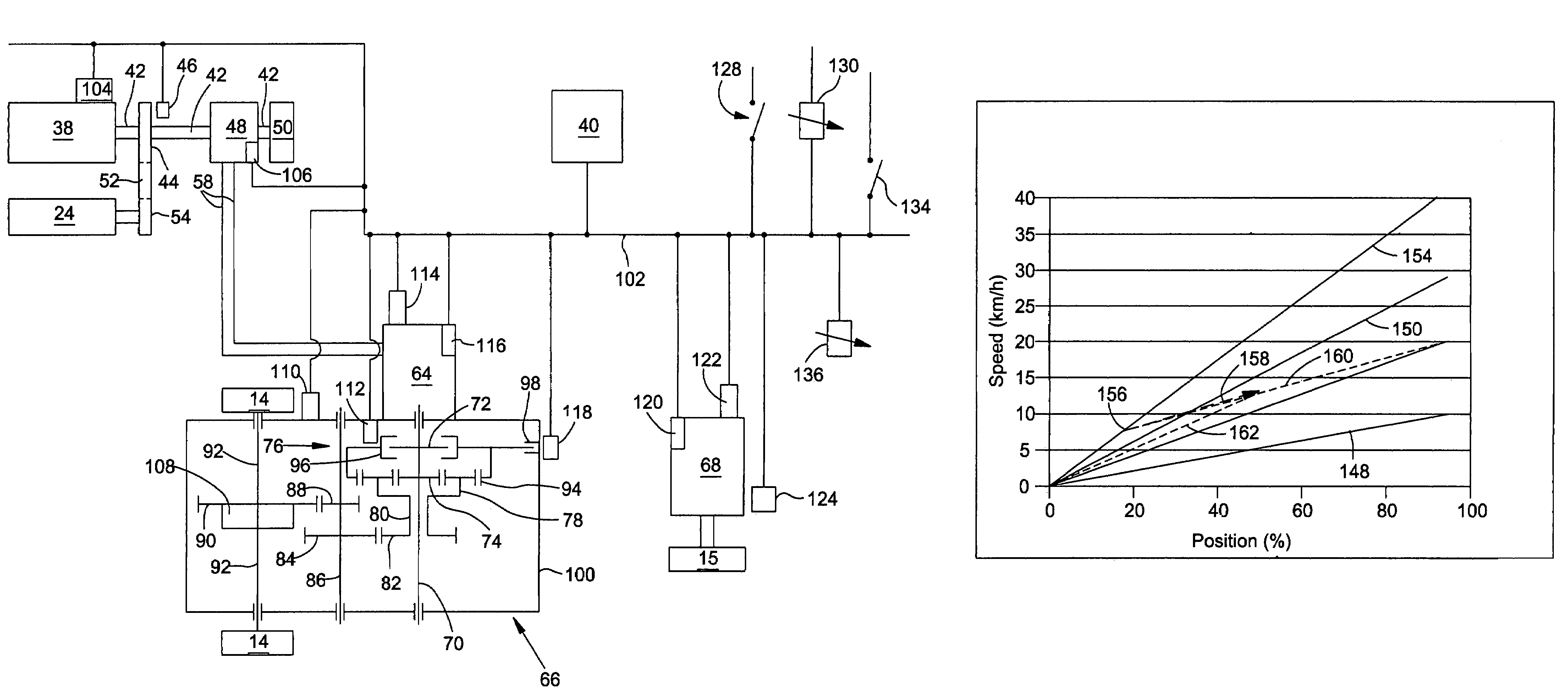
[0007]The propelling speed during operation is based upon the established relation between the desired speed input signal and the propelling speed. The operator can thus define a propelling speed between zero and a maximal speed assigned to this relation. If he wants to accelerate the working machine beyond the maximal speed of the established relation, the control unit is preferably operable in a manner allowing the operator to move the desired speed input means into a so-called acceleration zone defined in the vicinity of the maximal speed position of the desired speed input means. The control unit is then operable to instruct the actuators to accelerate the working machine beyond the maximal speed of the established relation. In this aspect of the invention, there is thus an acceleration zone at the end of the stroke of the desired speed input means.
[0008]If the desired speed input means is moved into said acceleration zone, the work vehicle accelerates until a speed desired by the operator is reached and then the operator is assumed to retract or pull back the desired speed input means. The relation between the desired speed signal and the propelling speed is established when the desired speed input signal is reduced for a predetermined time period after an acceleration. This relation is preferably determined by the control unit in a manner such that the speed of the working machine keeps constant until the position of the desired speed input means is in its final retracted position. Thus, an unwanted acceleration or deceleration is avoided. The final retracted position of the desired speed input means and the propelling speed of the working machine then achieved determine the new relation between the desired speed signal and the propelling speed established by the control unit. By appropriate selection of the final retracted position, the user can obtain the best relation. If he wants to drive with the achieved speed or slower, he positions the desired speed input means at the upper end of its range, while he can locate it in a lower portion of the range if a later acceleration is still desired.
[0009]When the working machine is starting from a zero speed, it is useful to use a first relation between the desired speed signal and the propelling speed with a relatively small slope. The operator can thus accelerate the machine smoothly. If he wants to achieve a higher speed than can be achieved with the first relation, he is able to move the desired speed input means into the maximal speed position, such that acceleration takes place.
[0010]When the working machine has been driving with an established relation between the desired speed input signal and the propelling speed for a predetermined time period, the operator may want to accelerate the machine again. Since it can be assumed that after this time period has passed, no large acceleration is required, at least when the position of the desired speed input means is below a certain threshold, the control unit is preferably operable to change then the relation between the desired speed signal and the propelling speed to another relation with a smaller slope. The working machine is thus accelerated more smoothly than with the old relation between the desired speed signal and the propelling speed. If the operator wants to accelerate faster, he can nevertheless move the desired speed input means into the acceleration zone. On the other hand, if the operator moves the desired speed input means into a lower speed position after driving for a predetermined time period with a constant speed, the established relation between the desired speed signal and the propelling speed is maintained. The machine can thus be decelerated in a short time.
[0011]The relation between the desired speed signal and the propelling speed is preferably linear, although non-linear relations, as cubic, exponential, logarithmic or any other suitable algebraic relations could be used. In a relatively simple embodiment, only a predetermined number of relations are available. On the other hand, it would be possible to provide an infinite number of relations between the desired speed signal and the propelling speed.

Problems solved by technology

A disadvantage however is that the operator has to perform the transmission ratio selection manually and that the machine has to stop before another transmission ratio can be selected.
Here, only two speed ranges of the operating lever are available, such that the propelling speed of the machine cannot always be controlled as sensitively as desired, for example when the machine is in the transport mode, but driving slowly downhill or uphill or on narrow lanes.

Method used


Image

  • Variable resolution single lever speed control for a hydrostatic transmission
  • Variable resolution single lever speed control for a hydrostatic transmission
  • Variable resolution single lever speed control for a hydrostatic transmission

Examples


Embodiment Construction

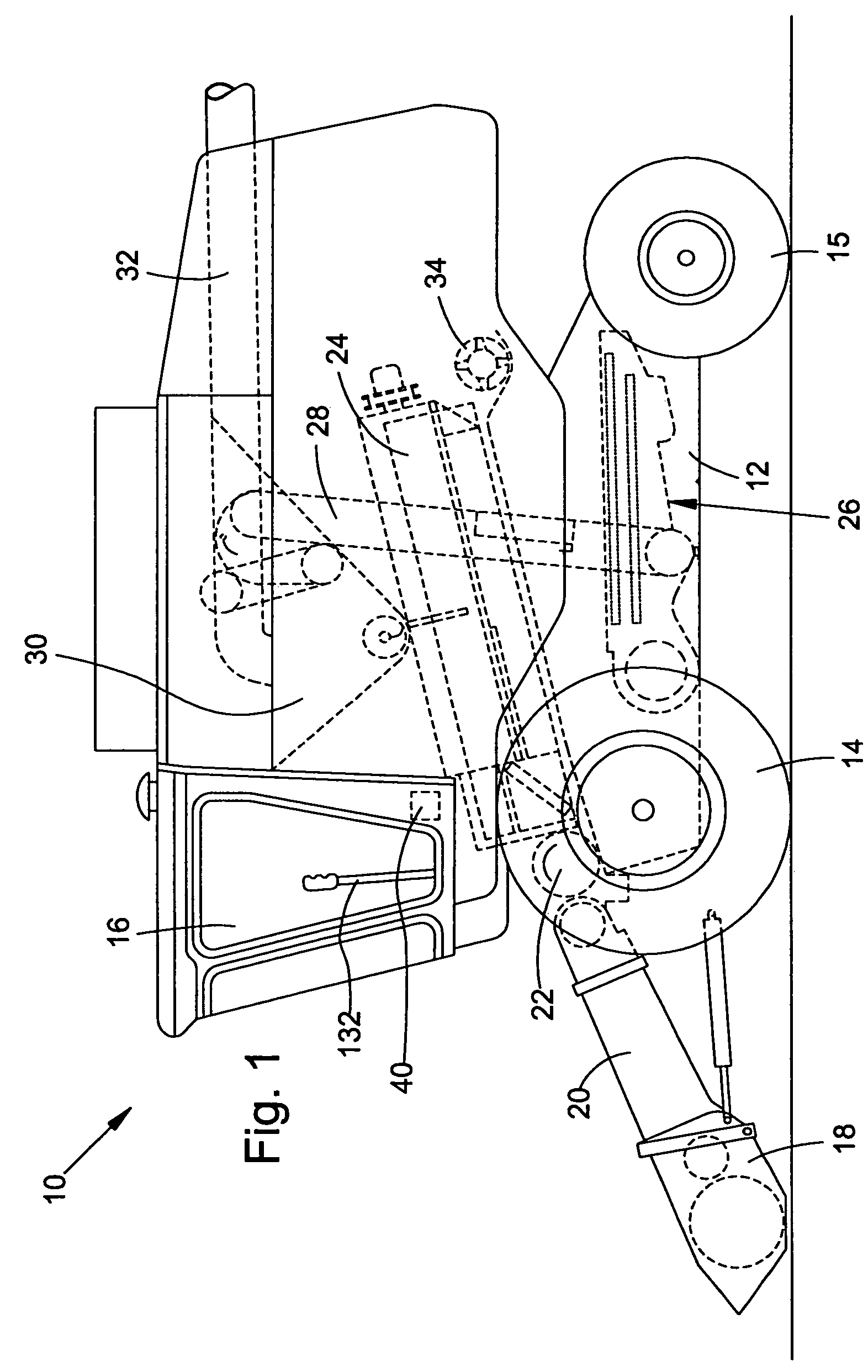
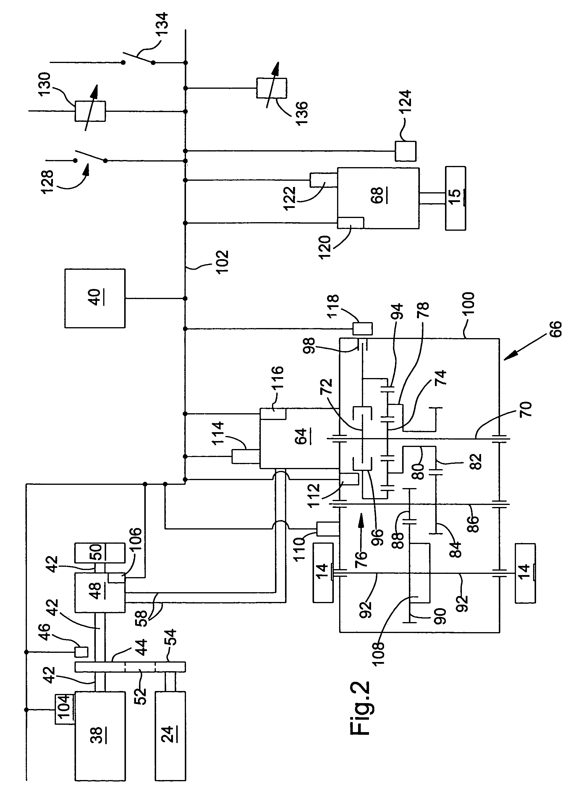
[0017]FIG. 1 shows a self-propelled agricultural working machine 10 in the form of a combine comprising a supporting structure 12 having ground engaging means 14, 15 in the form of wheels extending from the supporting structure. Instead of wheels, tracks could be used. The operation of the working machine 10 is controlled from operator's cab 16. A harvesting platform 18 is used for harvesting a crop and directing it to a feederhouse 20. The harvested crop is directed by the feederhouse 20 to a beater 22. The beater 22 directs the crop upwardly through an inlet transition section to an axial crop processing unit 24. The crop processing unit 24 threshes and separates the harvested crop material. Grain and chaff fall through grates on the bottom of the unit 24 to a cleaning system 26. The cleaning system 26 removes the chaff and directs the clean grain to a clean grain elevator 28. The clean grain elevator 28 deposits the clean grain in a grain tank 30. The clean grain in the tank 30 c...


PUM


Abstract

The invention refers to a self-propelled working machine comprising ground engaging means that are in drive connection with an engine for propelling the working machine, a desired speed input means having a range of movement for inputting a desired speed, a control unit receiving a desired speed signal from the desired speed input means and controlling an actuator that is influencing the speed of the ground engaging means based upon the desired speed signal.

Description

FIELD OF THE INVENTION[0001]The invention relates to self-propelled working machines comprising ground engaging means that are in drive connection with an engine for propelling the working machine, a desired speed input means having a range of movement for inputting a desired speed, a control unit operable to receive a desired speed signal from the desired speed input means and operable to control an actuator that is influencing the speed of the ground engaging means based upon the desired speed signal.BACKGROUND OF THE INVENTION[0002]Self-propelled harvesting machines, as combines, forage harvesters or cotton pickers, are usually propelled by a hydrostatic motor which is in hydraulic connection with a pump driven by a combustion engine. Such a harvesting machine is described in EP 0 819 562 A. There, the output speed of the hydrostatic motor is determined by a operator by means of an operating lever or drive lever mechanically controlling the position of a swash plate of the pump. ...

Claims


Application Information

Patent Timeline
Patent Type & Authority Patents(United States)
IPC IPC(8): F16H47/00
CPCA01D41/1274F16H61/47F02D31/007B60Y2200/22B60Y2200/221B60Y2200/222B60Y2200/41Y10T477/636F16H47/04F16H59/06F16H2047/045Y10T477/631
Inventor AMANN, CRAIGHEIM, DANIEL MARC
Owner DEERE & CO
Learn More