Brake adjusting mechanism

a technology of adjusting mechanism and brake, which is applied in the direction of mechanical equipment, fluid actuated brakes, transportation and packaging, etc., can solve the problems of not being able to achieve the effect of continuous tubes and non-uniform resistance to deformation of tubes over their entire length

Inactive Publication Date: 2006-12-07
THE BF GOODRICH CO
View PDF6 Cites 8 Cited by
  • Summary
  • Abstract
  • Description
  • Claims
  • Application Information

AI Technical Summary

Benefits of technology

[0007] The present invention provides an adjuster assembly for automatically maintaining a uniform release clearance (and therefore a uniform stroke) for brakes and similar equipment. The adjuster assembly comprises a continuous tube and an expansion member together having a combined length controlling the release clearance of selectively engageable friction parts. The expansion member has an expansion device frictionally engaging the interior of the continuous t

Problems solved by technology

Notwithstanding, there has been a problem of nonuniform resistance to deformation of the tube over its entire length.
Although the split tube o

Method used


Image

  • Brake adjusting mechanism
  • Brake adjusting mechanism
  • Brake adjusting mechanism

Examples


Embodiment Construction

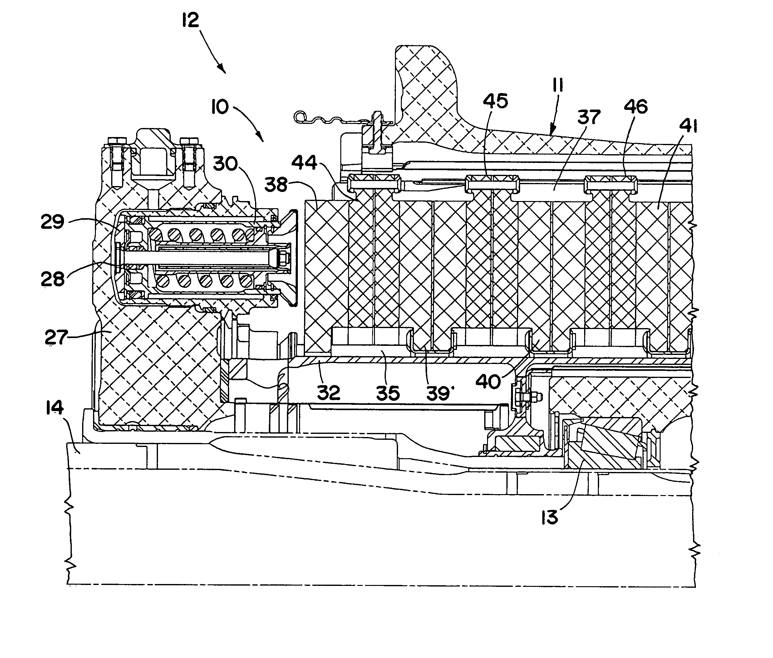
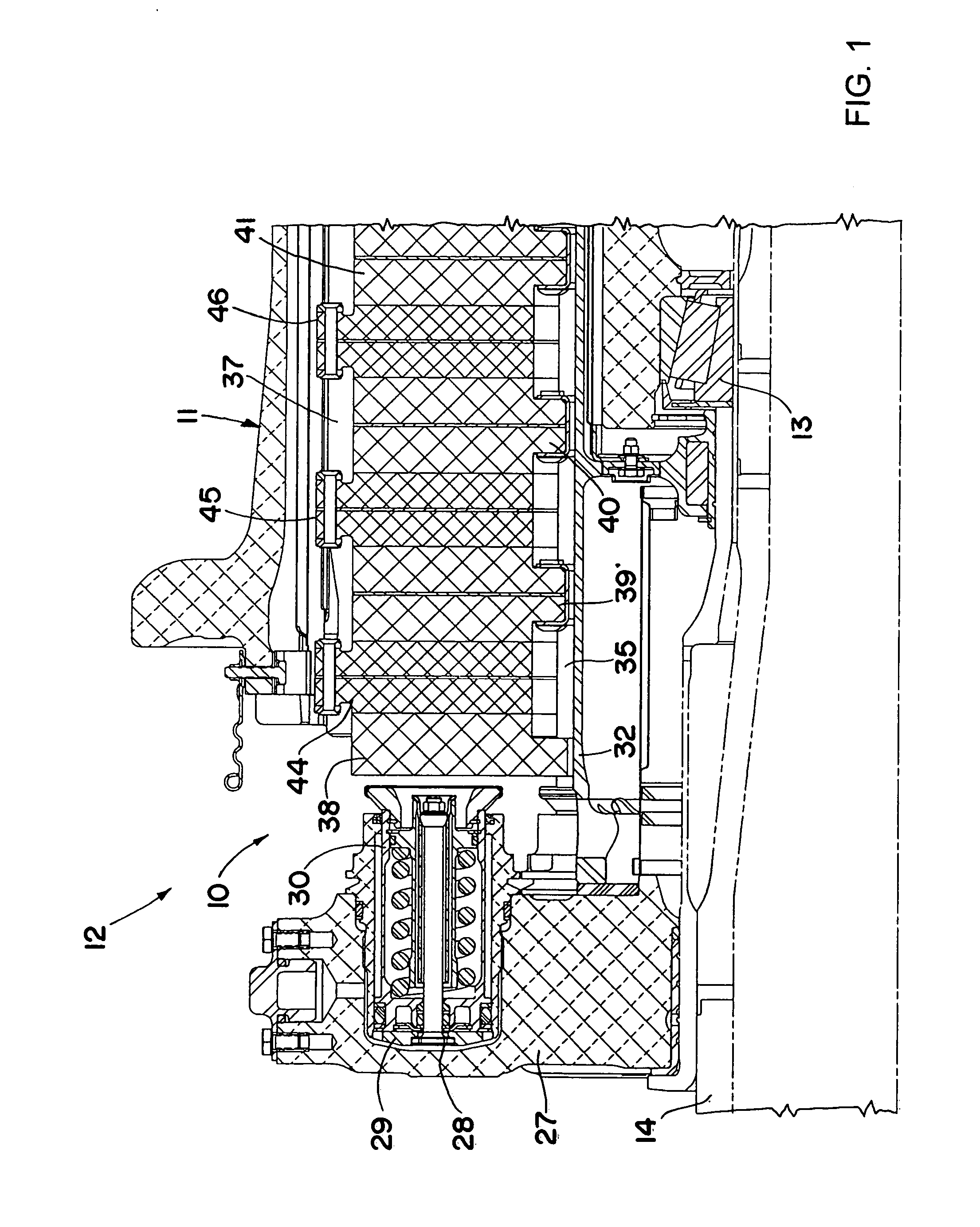
[0015] Referring to the drawings, wherein like reference numerals designate like or corresponding parts throughout the several views, there is shown in FIG. 1 an exemplary prior art friction brake mechanism 10 for use with a wheel 11. The brake mechanism and wheel form a wheel and brake assembly 12 particularly suited for use in an aircraft. As shown, the wheel is rotatably mounted by bearings 13 on an axle 14 that can be connected to a landing gear strut or truck in a conventional manner.

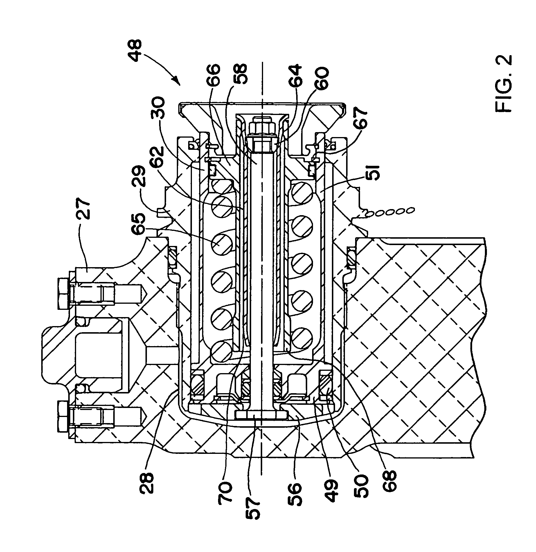
[0016] The brake mechanism 10 includes a piston housing 27 supported on the axle 14 in a conventional manner. The piston housing 27 has a plurality of circumferentially spaced bores 28 that receive cylinders 29 within which are slidably mounted pistons 30. The piston housing 27 has secured thereto a torque member 32 (commonly referred to as a torque tube or plate) that has an annular and radially outwardly extending reaction member (not shown) at its end opposite the piston housing.

[0017] The tor...


PUM


Abstract

An adjuster assembly (48) for automatically maintaining a uniform release clearance (and therefore a uniform stroke) for brakes and similar equipment. The adjuster assembly (48) comprises a continuous tube (62) and an expansion member (58) together having a combined length controlling the release clearance of selectively engageable friction parts. The expansion member (58) has an expansion device frictionally engaging the interior of the continuous tube (62) to effect progressive circumferential expansion of the continuous tube (62) when the expansion device is axially drawn through the continuous tube to compensate for wear of the friction parts during actuation and release of said selectively engageable parts. Unlike prior art adjuster assemblies, the continuous tube (62) advantageously has an end portion (70) processed differently from the balance of the continuous tube (62) for extending the usable portion of the continuous tube.

Description

FIELD OF THE INVENTION [0001] This invention relates to adjusting mechanisms for automatically maintaining a uniform release clearance (and therefore a uniform stroke) for brakes and similar equipment. Mechanisms of this type are commonly used in brake systems to compensate for wear of the brake linings and other brake parts and are popularly called “automatic brake adjusters.” Although the present invention is explained herein in connection with brakes, the mechanism has utility in other environments where similar wear compensation is needed such as in clutches. BACKGROUND OF THE INVENTION [0002] Brakes heretofore have included mechanical adjusters with special ratchets or friction dragging parts to provide adjustment for wear. Hydraulic adjusters utilizing the metering of hydraulic fluid and adjusters with deformable tubes have also been used. [0003] Also known are mechanical adjusters in which a deforming member is pulled through a ductile deformable tube. These adjusters have th...

Claims


Application Information

Patent Timeline
IPC IPC(8): F16D55/02F16D65/54F16D55/40F16D65/14
CPCF16D55/40F16D65/186F16D2121/02F16D2055/0058F16D65/543
Inventor SOELLNER, KENNETH ALAN
Owner THE BF GOODRICH CO
Why Eureka
Try Eureka