
Ultrahigh-speed static air pressure electric spindle parallel cooling structure

A cooling structure and air static pressure technology, applied in the direction of large fixed members, metal processing machinery parts, maintenance and safety accessories, etc., can solve the problems of complex processing and assembly technology, low convective heat transfer capacity, heating of electric spindle parts, etc., to achieve Avoid the reverse heating phenomenon, improve the convective heat transfer coefficient, and increase the effect of the flow rate

Active Publication Date: 2017-10-27
HEFEI INSTITUTES OF PHYSICAL SCIENCE - CHINESE ACAD OF SCI
View PDF2 Cites 2 Cited by
  • Summary
  • Abstract
  • Description
  • Claims
  • Application Information

AI Technical Summary

Problems solved by technology

Generally, the ultra-high-speed air static pressure electric spindle is thermally balanced by forced water cooling. At present, the forced water cooling of the electric spindle generally adopts structures such as spiral water tanks and broken-line cooling water channels to make the cooling water circulate in series in the electric spindle. Or step-by-step cooling of air static pressure thrust bearings, air static pressure radial bearings and stator coils of built-in motors, etc. This cooling structure makes cooling water flow in series with large flow resistance, low flow rate, and low convective heat transfer capacity
Due to the continuous heating of the series cooling water during the flow process, the cooling water temperature is too high to heat the electric spindle parts, which reduces the cooling effect
In addition, this cooling structure leads to complex structure of the spindle, complex processing and assembly process, and high cost

Method used


Image

  • Ultrahigh-speed static air pressure electric spindle parallel cooling structure
  • Ultrahigh-speed static air pressure electric spindle parallel cooling structure

Examples


Embodiment Construction

[0016] The embodiments of the present invention are described in detail below. This embodiment is implemented on the premise of the technical solution of the present invention, and detailed implementation methods and specific operating procedures are provided, but the protection scope of the present invention is not limited to the following implementation example.

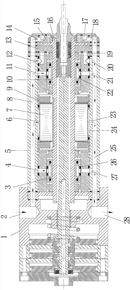
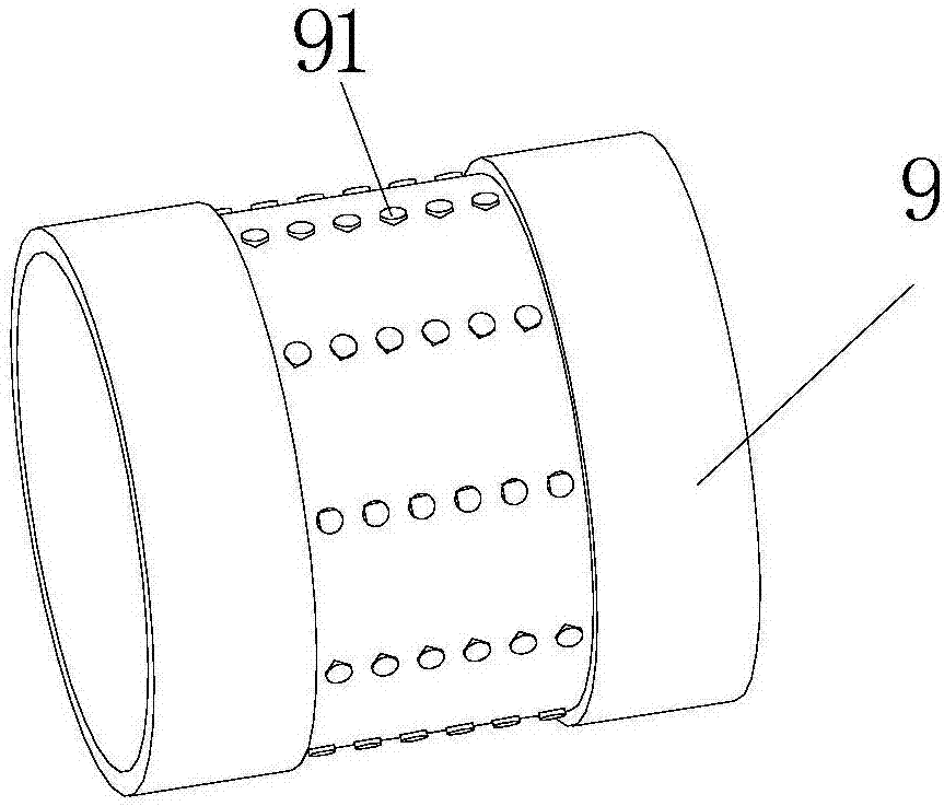
[0017] see Figure 1 to Figure 2 , this embodiment discloses an ultra-high-speed aerostatic electric spindle parallel cooling structure, the electric spindle includes a shaft core 16 and a plurality of heat-generating components arranged in parallel outside the shaft core 16, and the plurality of heat-generating components include two radial bearings , two thrust bearings and stator 7, two radial bearings are respectively left radial bearing 3, right radial bearing 10, and two thrust bearings are respectively left thrust bearing 13 and right thrust bearing 15. Multiple heat-generating components are covered with a...


PUM


Abstract

The invention discloses an ultrahigh-speed static air pressure electric spindle parallel cooling structure. An electric spindle comprises a core and a plurality of heating components parallelly sleeving the core, an annular shell externally wraps the heating components, the cooling structure comprises a main water inlet channel, a plurality of branch water inlet channels, a plurality of cooling cavities, a plurality of branch water outlet channels and a main water outlet channel, the main water inlet channel and the main water outlet channel are arranged in the shell, are straight channels and extend along the axial direction of the core, the corresponding annular cooling cavities are formed in the heating components, each cooling cavity is communicated with the main water inlet channel through the corresponding branch water inlet channel and communicated with the main water outlet channel through the corresponding branch water outlet channel, and the branch water inlet channels and the branch water outlet channels extend along the radial direction of the core. The cooling structure has the advantages of simple structure, convenience in machining, high cooling efficiency and capabilities of simplifying machining and assembling process and saving production cost.

Description

technical field [0001] The invention relates to the technical field of electric spindle cooling, in particular to an ultra-high-speed aerostatic electric spindle parallel cooling structure. Background technique [0002] High-end CNC machine tools are developing in the direction of high precision, high efficiency and high speed. Among them, the ultra-high-speed aerostatic electric spindle component is one of the main components to realize high-precision and high-efficiency cutting technology, and is the core functional component of high-end CNC machine tools. The ultra-high-speed aerostatic electric spindle is mainly used in the fields of micro-milling, micro-grinding and micro-drilling, and the maximum speed is generally not lower than 100,000r / min. Due to the heating of the motor stator coil during the rotation of the electric spindle, the electromagnetic eddy current heating of the motor rotor, and the high-speed airflow viscous shear friction heating of the micron gap of ...

Claims


Application Information

Patent Timeline
Patent Type & Authority Applications(China)
IPC IPC(8): B23B19/02B23Q11/12
CPCB23Q1/70B23Q11/12B23Q11/127
Inventor 高思煜施云高孔令成叶晓东陈红张孝俣骆栋栋夏明
Owner HEFEI INSTITUTES OF PHYSICAL SCIENCE - CHINESE ACAD OF SCI
Learn More