

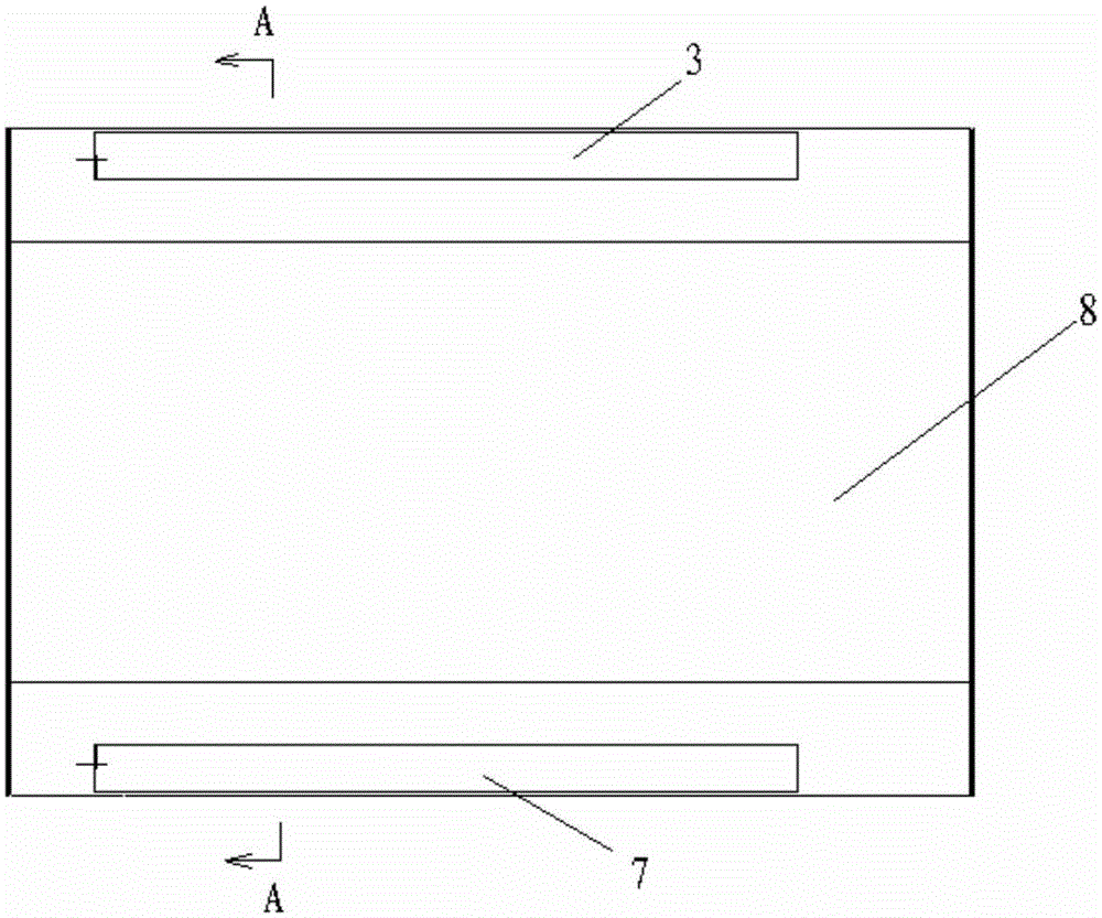
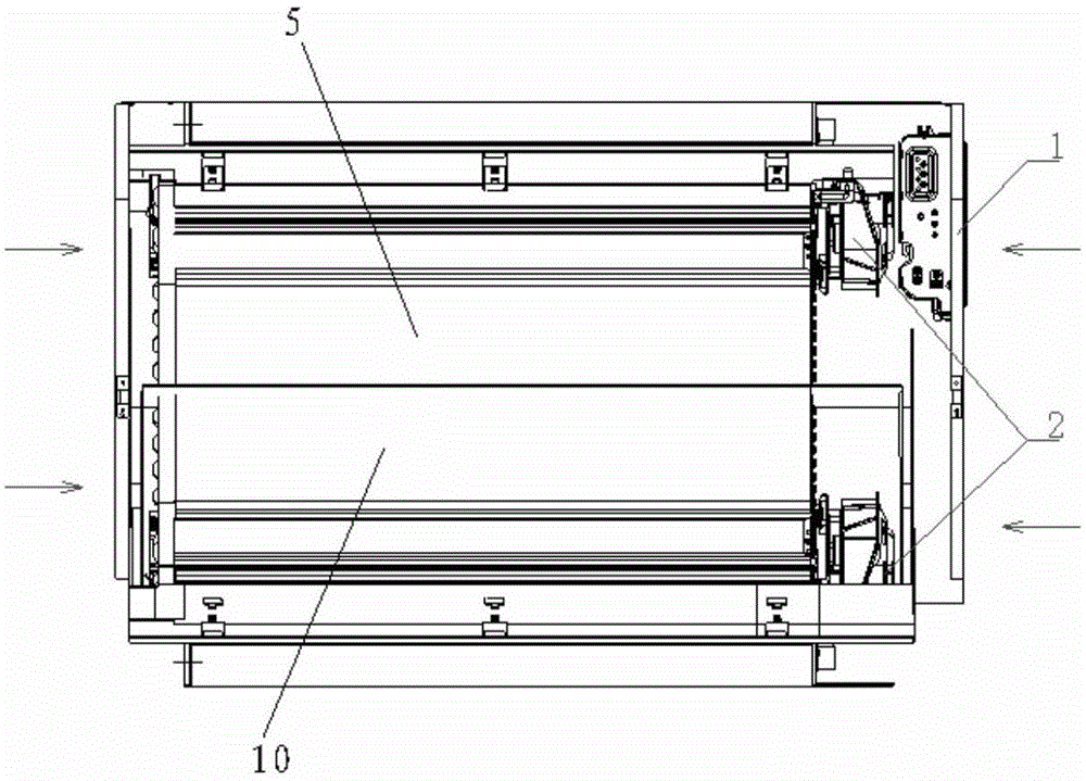
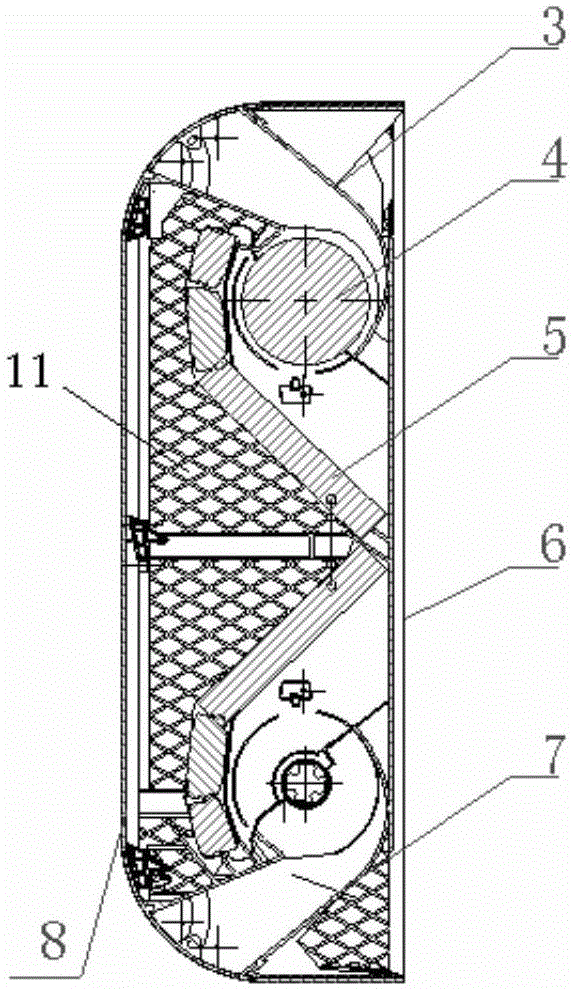
Upper and lower exhaust wall-mounted air conditioning indoor unit
An air-conditioning indoor unit and air-out wall-mounted technology, which is applied in air-conditioning systems, heating methods, space heating and ventilation, etc., can solve problems such as insufficient air volume, uneven distribution of indoor temperature field, and poor indoor heat exchange effect, and achieve Increase the air volume, uniform temperature field distribution, and intensify the effect of air turbulence
- Summary
- Abstract
- Description
- Claims
- Application Information
AI Technical Summary
Problems solved by technology
Method used
Image

Examples
Embodiment Construction
[0027] The specific implementation manners of the present invention will be further described in detail below in conjunction with the accompanying drawings and examples. The following examples are used to illustrate the present invention, but are not intended to limit the scope of the present invention.
[0028] In describing the present invention, it is to be understood that the terms "upper", "lower", "front", "rear", "vertical", "horizontal", "top", "bottom", "inner", " The orientation or positional relationship indicated by "outside", etc. is based on the orientation or positional relationship shown in the drawings, and is only for the convenience of describing the present invention and simplifying the description, rather than indicating or implying that the referred device or element must have a specific orientation, so as to Specific orientation configurations and operations, therefore, are not to be construed as limitations on the invention. In addition, the terms "fir...
PUM
 Abstract
Description
Claims
Application Information