Method of manufacturing a liquid crystal alignment film utilizing long-throw sputtering

Inactive Publication Date: 2006-12-07
UNITED MICRODISPLAY OPTRONICS CORP
View PDF8 Cites 4 Cited by
  • Summary
  • Abstract
  • Description
  • Claims
  • Application Information

AI Technical Summary

Benefits of technology

[0011] The claimed invention uses inorganic alignment materials to form a target, and utilizes sputtering to manufacture a LC alignment film. Not only does the claimed invention eliminate the problems of the alignment film passing the reliability test, the trace of rubbing cloth, and the agreement of alignment film, but it also improves the breakthrough and quality of the alignment film to reduce the cost.

Problems solved by technology

However, in some large-sized, high-density LC applications, problems including viewing angle, contrast, display uniformity, response time, etc. are still to be overcome.
For example, because the rubbing method is a contact technique, debris can be generated during the rubbing process resulting in a low process yield.
In addition, as the roller or brush rubs the surface of the display, electrostatic charges can build up which may discharge through the thin film transistors (TFT) resulting in a lowering of the process yield.
Furthermore, the PI organic film cannot easily pass the reliability test that will influence the quality of TFT.
Thus, choice of materials that are suitable for use in the rubbing process is limited.

Method used


Image

  • Method of manufacturing a liquid crystal alignment film utilizing long-throw sputtering
  • Method of manufacturing a liquid crystal alignment film utilizing long-throw sputtering
  • Method of manufacturing a liquid crystal alignment film utilizing long-throw sputtering

Examples


Embodiment Construction

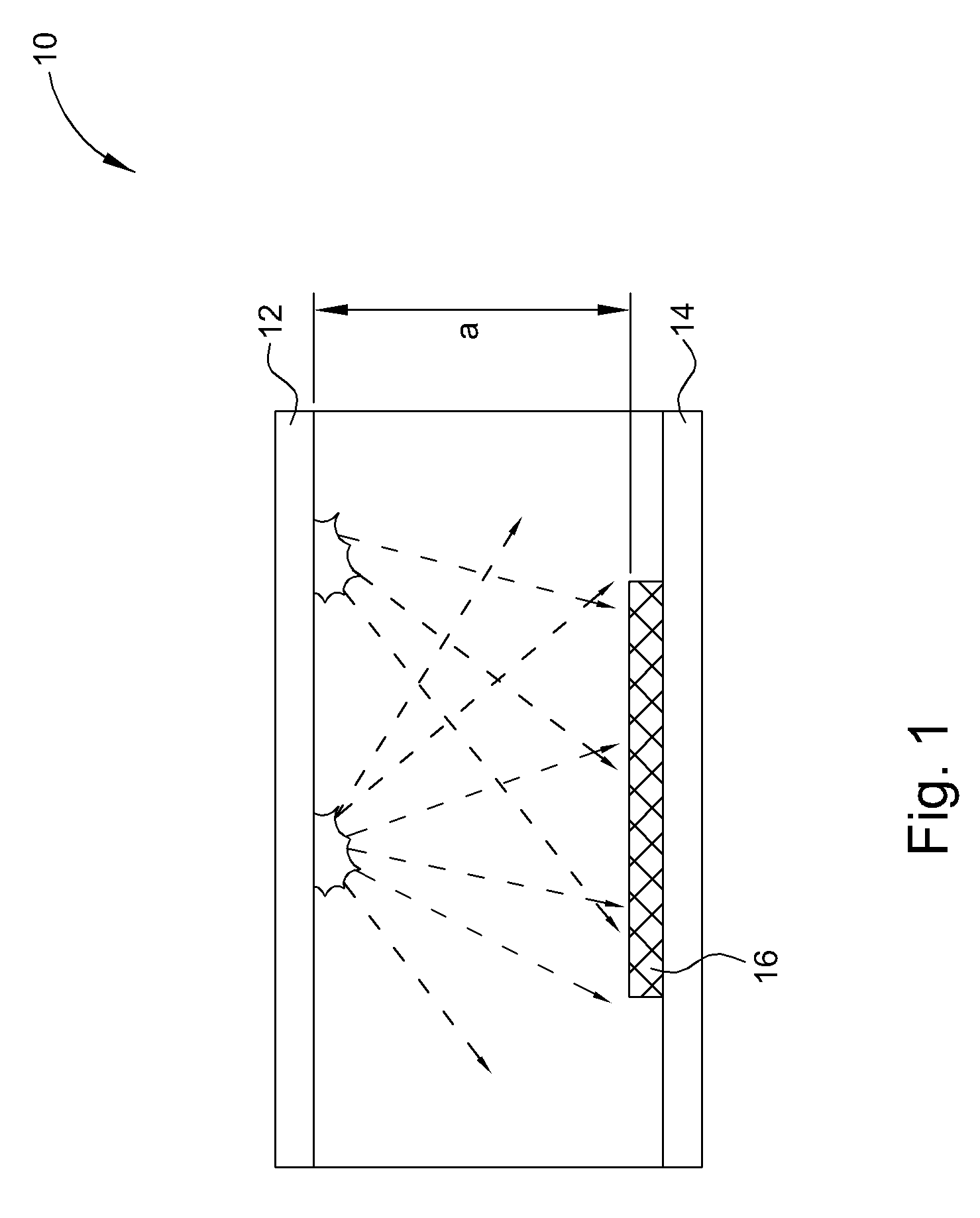
[0017] Please refer to FIG. 1 that is a schematic diagram of manufacturing a LC alignment film utilizing the general sputtering technique. As shown in FIG. 1, a chamber 10 includes a target 12 and a substrate carrier 14, and a substrate 16 put on the substrate carrier 14. Between the substrate 16 and the target 12 is a distance “a”. Then a sputtering process is performed for manufacturing an LC alignment film. Dotted line arrows shown in FIG. 1 illustrate the directions and distances of the sputtering ions. However, the distance “a” between the target 12 and substrate 16 is about 10 cm so that an angle of the sputtering species depositing on the substrate 16. The substrate 16 is too broad to permit various orientational grooves on the LC alignment of the substrate 16 and influences the angle of the LC molecules and the surface of the alignment film 16, and reduces the quality and yield of the LC alignment film.

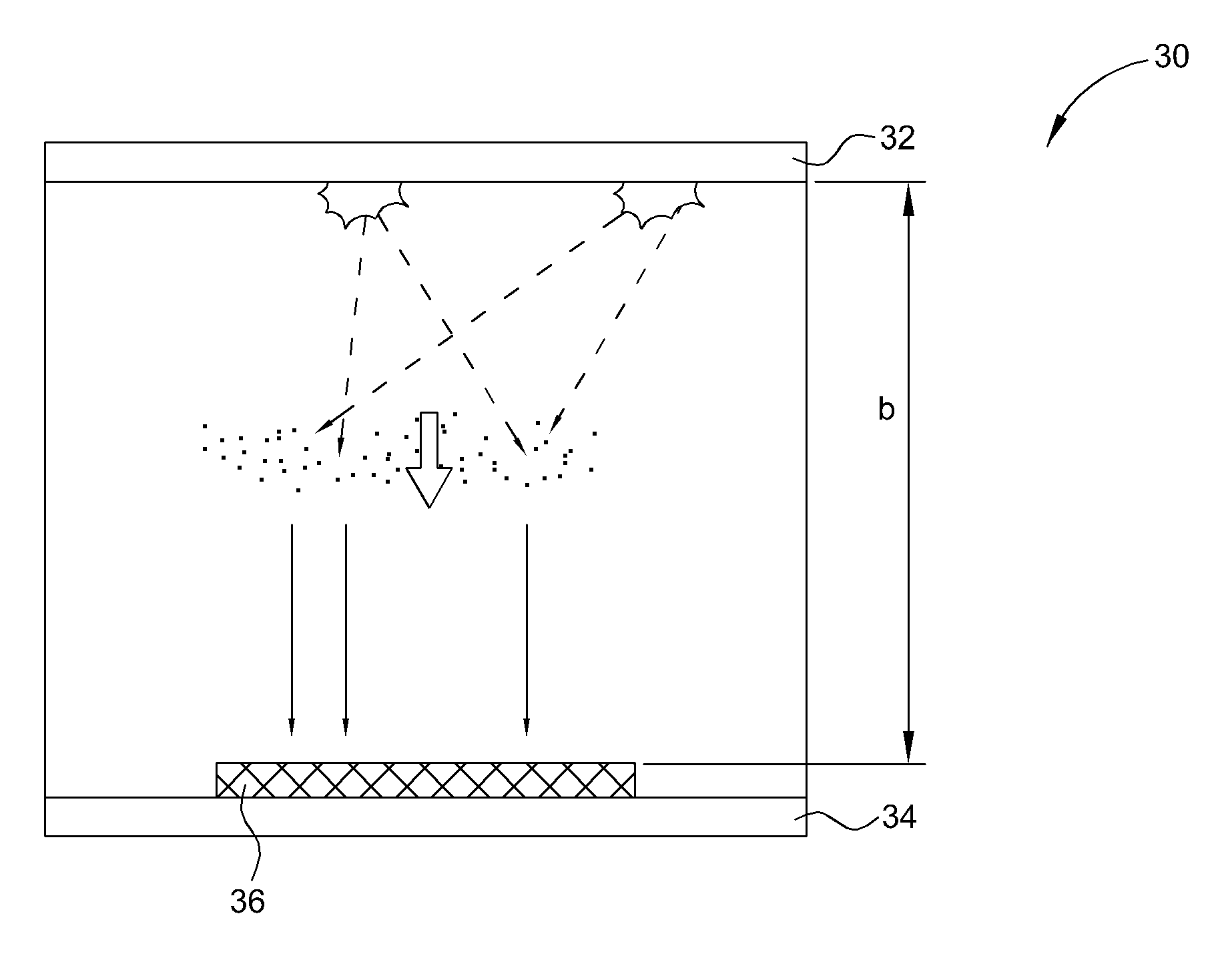
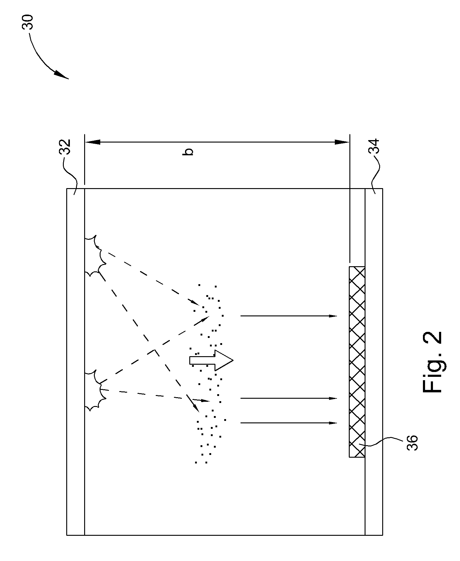
[0018] Please refer to FIG. 2 and FIG. 3 that are schematic diagrams of ...


PUM

PropertyMeasurementUnit
Angleaaaaaaaaaa
Lengthaaaaaaaaaa
Distanceaaaaaaaaaa

Abstract

The present invention provides a method of manufacturing an LC alignment film utilizing long-throw sputtering. The method includes putting a substrate on a substrate carrier in a chamber, utilizing high-density plasma to bombard a target over the substrate to produce sputtering species, and providing a bias voltage in the chamber. Nearly vertical directional sputtering species are deposited on the surface of the substrate to form an LC alignment film. The distance between the target and the substrate is more than 20 cm.

Description

BACKGROUND OF INVENTION [0001] 1. Field of the Invention [0002] The invention relates to manufacturing a liquid crystal (LC) alignment film, and more particularly, to utilizing long-throw sputtering or a collimator to manufacture a liquid crystal alignment film. [0003] 2. Description of the Prior Art [0004] Liquid Crystal (LC) displays are widely used in various applications. Generally, the image quality of small-sized LC displays is close to the image quality of conventional CRT displays. However, in some large-sized, high-density LC applications, problems including viewing angle, contrast, display uniformity, response time, etc. are still to be overcome. In the manufacture of LCD devices, as known in the art, the alignment of LC molecules sandwiched between transparent electrodes formed on opposed substrate plates is critical. To obtain better contrast, the orientation of the LC molecules must be uniformly controlled. [0005] The alignment types of the LC molecules are generally di...

Claims


Application Information

Patent Timeline
IPC IPC(8): C23C14/00
CPCC23C14/34C23C14/225
Inventor KUAN, TA-SHUANGCHANG, YI-MINGLIN, CHIA-TECHAN, CHIA-TSUNG
Owner UNITED MICRODISPLAY OPTRONICS CORP
Why Eureka
Try Eureka