Method for detecting 3D measurement data using allowable error zone

a technology of error zone and measurement data, applied in the direction of measurement devices, instruments, material analysis, etc., can solve the reliability problem of whether the selected points are actually points required for comparison, and the user cannot be certain whether the comparison result for the measurement data is accura

Inactive Publication Date: 2006-12-07
INUS TECH
View PDF2 Cites 20 Cited by
  • Summary
  • Abstract
  • Description
  • Claims
  • Application Information

AI Technical Summary

Benefits of technology

[0016] It is an object of the present invention to provide a method of detecting 3D measurement data using an allowable error zone capable of reliably locating points on measurement data that is to be matched to a relevant reference geometry so as to detect a reference geometry on the measurement data that corresponds to a reference geometry defined by the design data.

Problems solved by technology

However, the above related art measuring method has the problem of consuming much time in measuring an object because a user must manually select object points to be compared from measurement data.
Though a method of automatically selecting object points to be compared from measurement data is provided, there still exists the reliability problem of whether the selected points are actually points required for comparison.
Accordingly, a user cannot be certain whether the comparison result for the measurement data is accurate.

Method used


Image

  • Method for detecting 3D measurement data using allowable error zone
  • Method for detecting 3D measurement data using allowable error zone
  • Method for detecting 3D measurement data using allowable error zone

Examples


Embodiment Construction

[0037] Reference will now be made in detail to a preferred embodiment of the present invention.

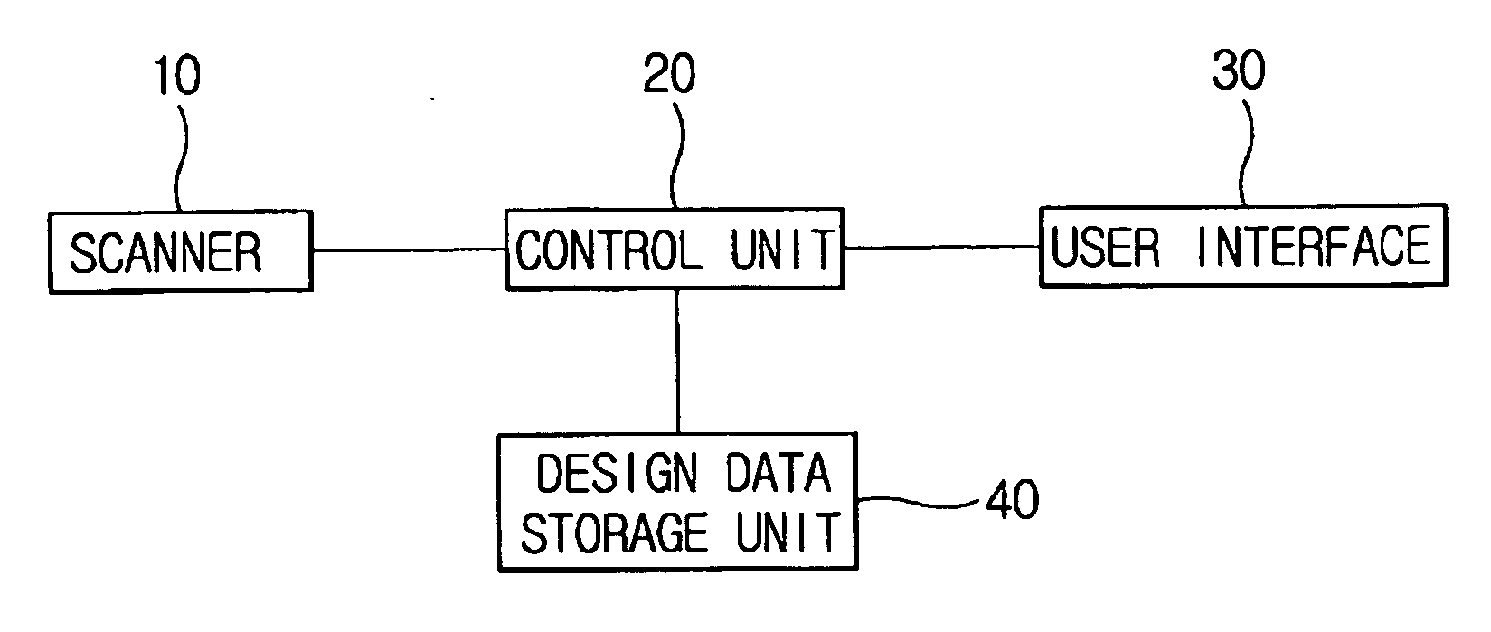
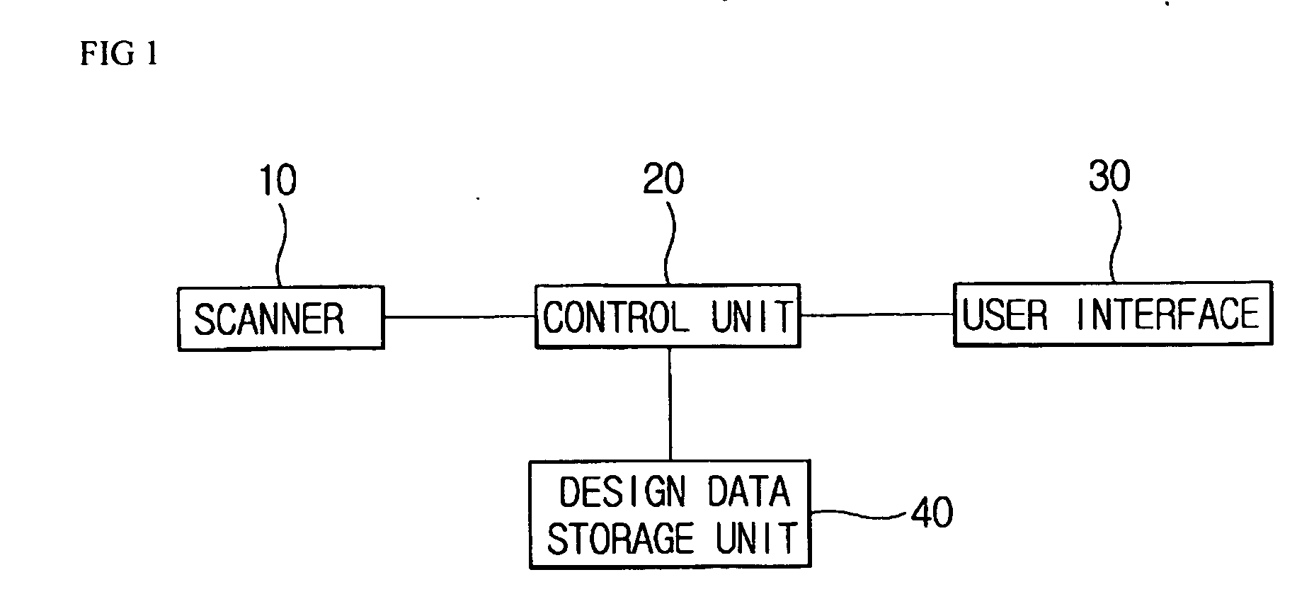
[0038]FIG. 1 is a block diagram of a system for detecting 3D measurement data using an allowable error zone according to the present invention.

[0039] Referring to FIG. 1, the system includes a scanner (10) for measuring an object to be measured, a control unit (20) for controlling the system on the whole, a user interface (30) for providing an interface with a user, and a design data storage unit (40) for storing design data of the object.

[0040] The scanner (10) is a device for measuring the object and obtaining measurement data. The scanner (10) may be a non-contact 3D scanner.

[0041] The control unit (20) analyzes the design data of the object, sets auxiliary geometry data for measurement from the design data of the object, sets an allowable error zone of the auxiliary geometry data for measurement on the basis of allowable error information inputted from a user interface (30), detect...


PUM

PropertyMeasurementUnit
geometric shapeaaaaaaaaaa
angleaaaaaaaaaa
circumferenceaaaaaaaaaa

Abstract

A method of detecting 3D measurement data using an allowable error zone is provided. The method detects 3D measurement data that corresponds to a preset measurement allowable error zone for each basic diagram when detecting 3D measurement data. For that purpose, a control unit generates auxiliary geometry data from a design data storage unit on the basis of analysis information of the design data; sets an allowable error zone for measurement in the auxiliary geometry data on the basis of allowable error information inputted from a user interface; controls a coordinate system of measurement data to coincide with a coordinate system of design data of the object; extracts candidate point groups included in the allowable error zone for measurement of the auxiliary geometry data from the measurement data; and fits the candidate point groups extracted from the candidate point groups included in the allowable error zone for measurement to output the fitted candidate point groups to the user interface.

Description

BACKGROUND OF THE INVENTION [0001] 1. Field of the Invention [0002] The present invention relates to a method of automatically detecting 3-dimensional (3D) measurement data, and more particularly, to a method of detecting 3D measurement data that corresponds to a preset allowable error zone for each basic diagram when detecting 3D measurement data. [0003] 2. Description of the Related Art [0004] Measurements using a 3D scanner can be performed using a contact method of directly contacting an object to be measured. Also, shape information of an object can be obtained using a non-contact method of digitally processing an image obtained by photographing the object using imaging equipment without physically contacting the object. [0005] The measurement using a 3D non-contact type scanner is used for obtaining shape information of an object that is easily damaged when external force is applied to the object to be measured or a high-precision, small-sized component, as in cases of produci...

Claims


Application Information

Patent Timeline
Patent Type & Authority Applications(United States)
IPC IPC(8): G01N21/86G01V8/00
CPCG01B21/045G01N2021/9516G01N21/9515G06V10/10
Inventor BAE, SEOCK HOONLEE, DONG HOONKIM, SEUNG YOBCHO, SUNG WOOK
Owner INUS TECH
Why Eureka
Try Eureka