Coupling mechanism for anti-roll bar

a coupling mechanism and anti-roll bar technology, applied in mechanical devices, torque springs, transportation and packaging, etc., can solve the problems of large amount of energy required for the mechanism, bulky and expensive,

Active Publication Date: 2006-12-07
BWI +1
View PDF0 Cites 41 Cited by
  • Summary
  • Abstract
  • Description
  • Claims
  • Application Information

AI Technical Summary

Benefits of technology

[0021] Thus, control of the actuator may be effected in simple manner, as it is sufficient for the actuator to displace the elongate element until it is detected that this has arrived in a stop position. Preferably, the said actuator is able to position the said at least one elongate element in a plurality of states corresponding, for the said elastic flexion deformation, to a plurality of flexion stiffnesses of the

Problems solved by technology

This mechanism therefore requires a large amoun

Method used


Image

  • Coupling mechanism for anti-roll bar
  • Coupling mechanism for anti-roll bar
  • Coupling mechanism for anti-roll bar

Examples


Embodiment Construction

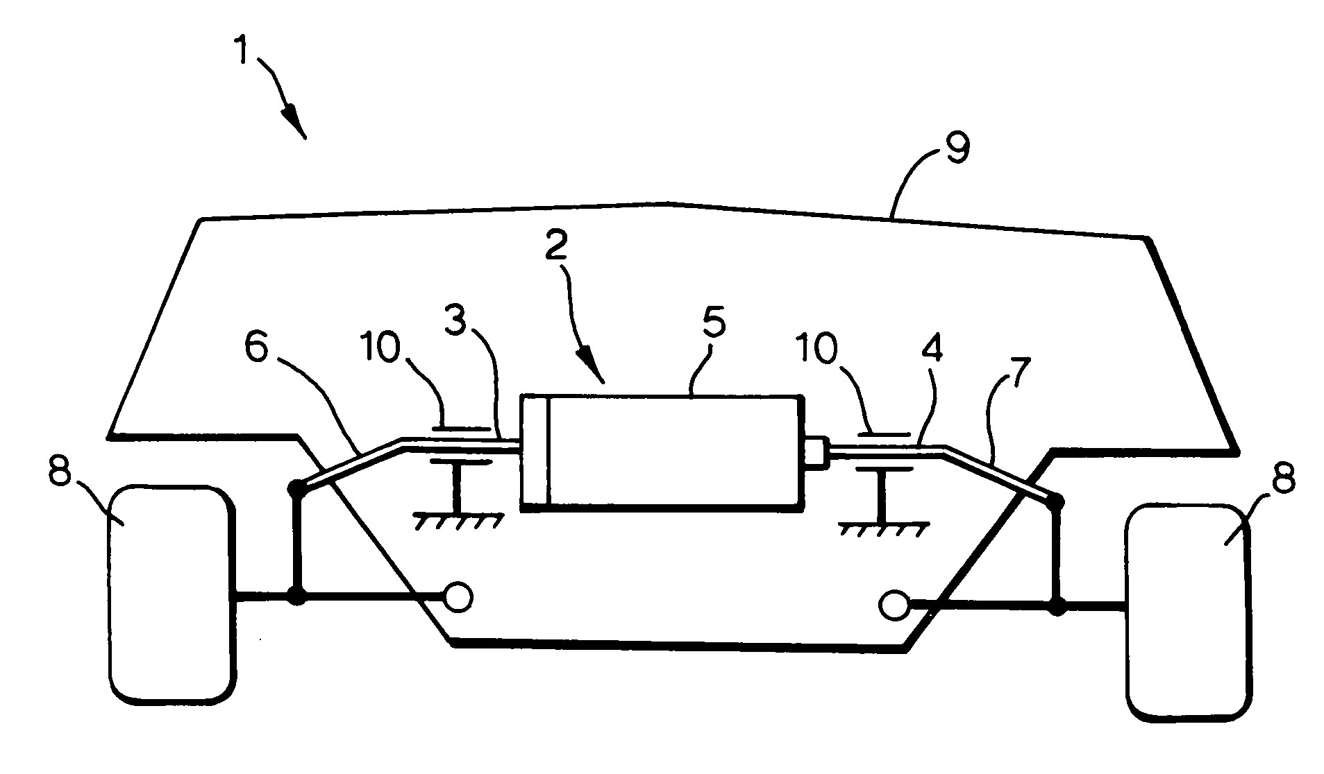
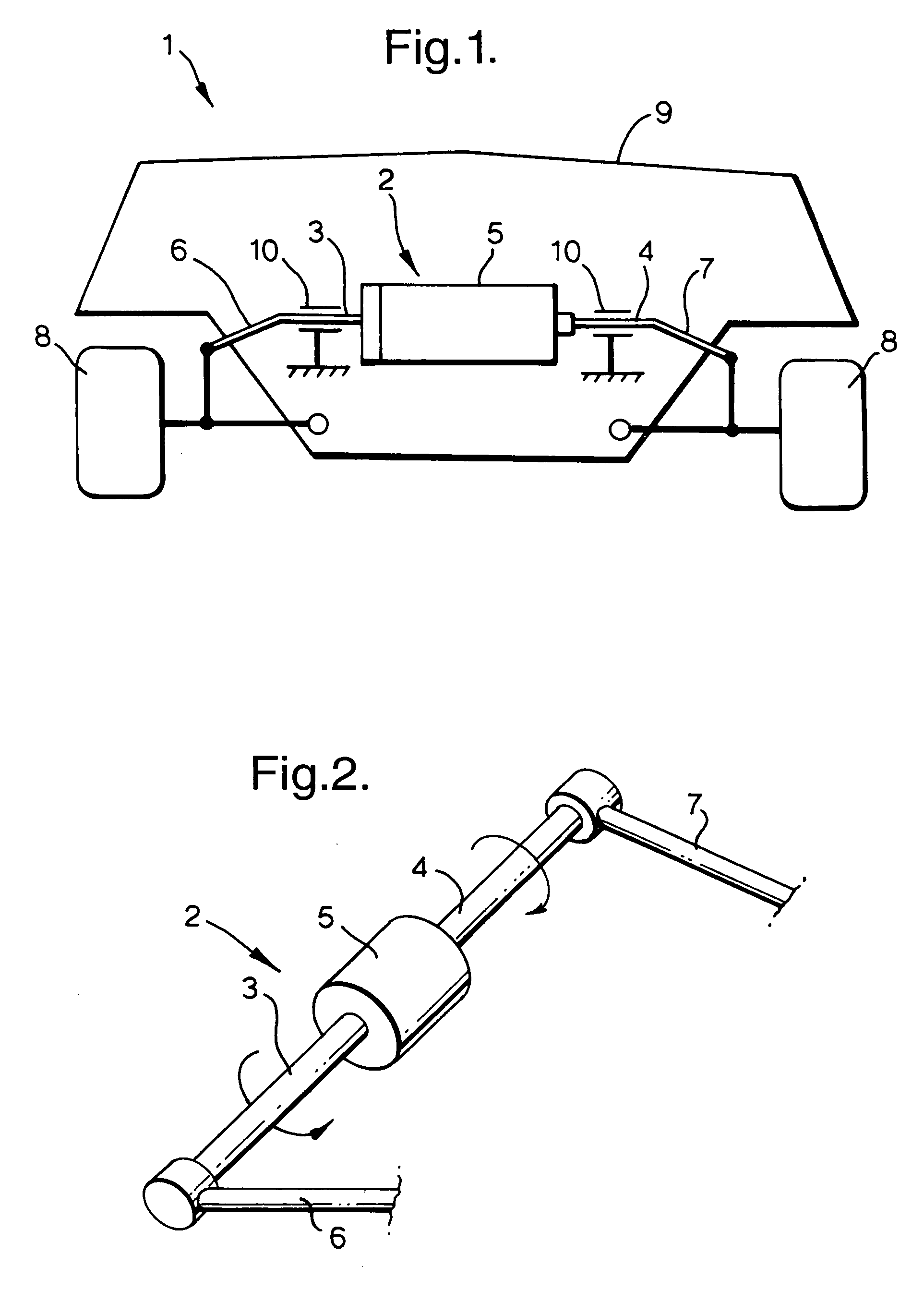
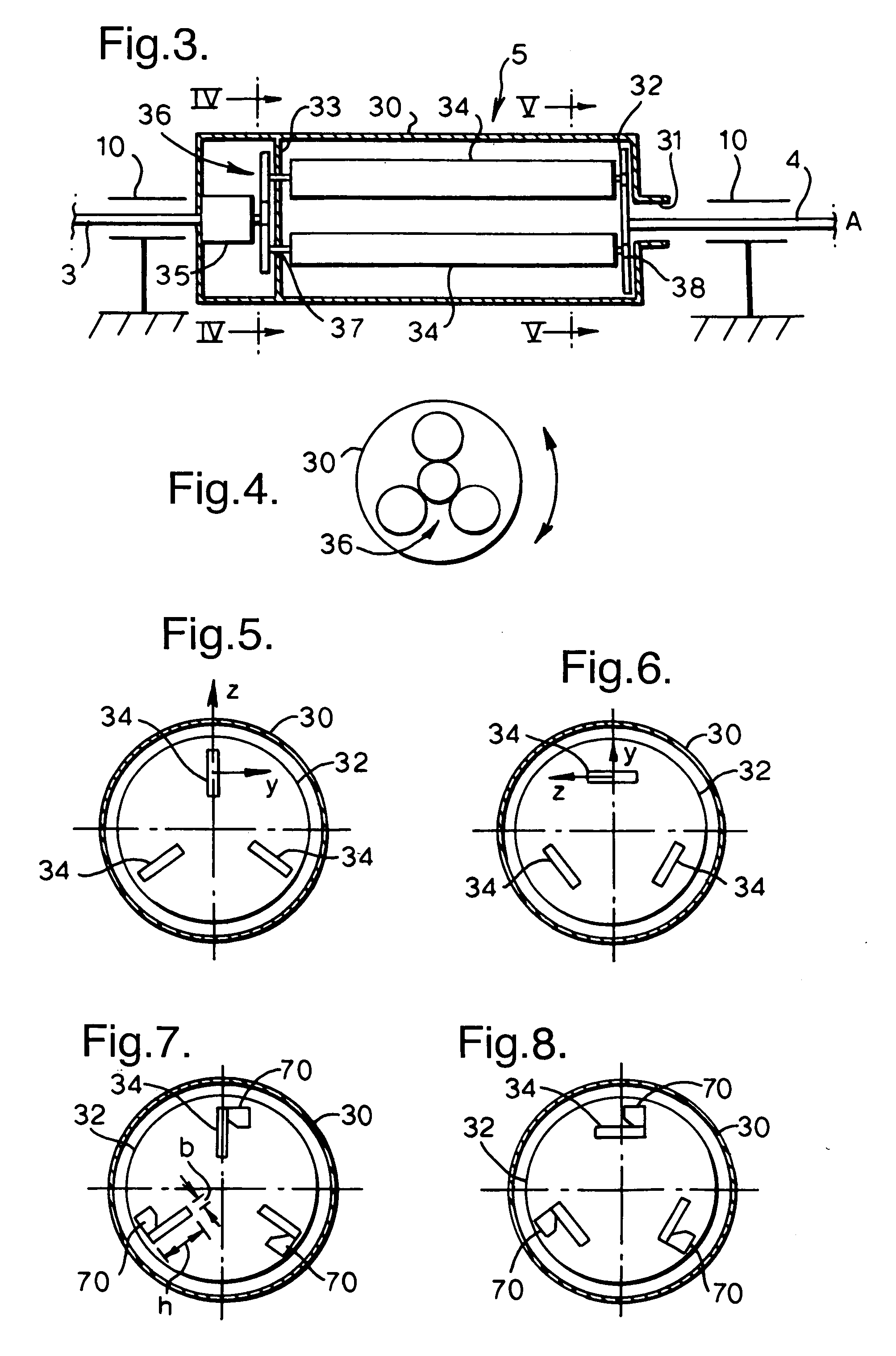
[0047] With reference to FIGS. 1 and 2, the vehicle 1 is fitted with a semi-active anti-roll device 2. The anti-roll device 2 comprises a central portion composed of two half-bars 3 and 4 aligned along an axis A (FIG. 3) parallel with the axis of the set of wheels 8. This may be the front and / or rear set of wheels. The half-bars 3 and 4 are connected by a coupling mechanism 5.

[0048] The device 2 also comprises two lateral arms 6 and 7 connected to the ends of the half-bars 3 and 4 so as to form a U-shaped torsion bar. The ends of the lateral arms 6 and 7 are coupled to supports of the wheels 8, for example to the torque rods of the wheels 8. The half-bars 3 and 4 are coupled to the body 9 of the vehicle 1 by means of connecting pivot bearings 10.

[0049] When, in a bend, the body 9 leans at a given angle of roll α, the anti-roll device is in a state of torsion at an angle of torsion per unit length θ which depends on the angle α.

[0050]FIGS. 9, 10 and 11 show the relationship betwee...


PUM


Abstract

Coupling mechanism for a vehicle anti-roll bar comprising a first piece able to be fixed to a first half-bar, a second piece able to be fixed to a second half-bar, the second piece being so arranged as to be moveable in rotation about an axis of rotation A relative to the first piece. The mechanism includes at least one elastically deformable elongate element coupled to the first and second pieces so that relative rotation of the first and second pieces about the axis of rotation A causes elastic flexion deformation of the at least one elongate element, the mechanism including an actuator able to position the at least one elongate element in a first state in which the said at least one elongate element presents a first flexion stiffness for the said elastic flexion deformation, and a second state in which the said at least one elongate element presents a second flexion stiffness for the said elastic flexion deformation.

Description

TECHNICAL FIELD [0001] The present invention relates to vehicle anti-roll bars. More particularly, the present invention relates to an electromechanical coupling mechanism for an anti-roll bar. BACKGROUND OF THE INVENTION [0002] When a vehicle turns, the lateral acceleration produces a moment, orientated with respect to the longitudinal axis of the vehicle, causing a change in the seating of the vehicle body: the torque rods of the wheels positioned inside the bend are subject to a different load from that to which the torque rods situated on the outside of the bend are subject. Relative to the body, the wheel supports are displaced by a different amount along the (virtually vertical) axes of the torque rods. Relative to the axis passing through the wheels of a set of wheels, the body is inclined by an angle known as the angle of roll. [0003] In order to reduce the roll of a vehicle, it is known to provide the front set of wheels and / or the rear set of wheels with a passive anti-rol...

Claims


Application Information

Patent Timeline
IPC IPC(8): B60G21/055B60G11/20
CPCB60G21/0558B60G2202/1351B60G2202/1362B60G2206/722B60G2204/8306B60G2206/427B60G2204/82
Inventor BARTH, LAURENTDELAYRE, XAVIER
Owner BWI
Why Eureka
Try Eureka