

Device for the control of fluorescent lamps in a lighting arrangement
- Summary
- Abstract
- Description
- Claims
- Application Information
AI Technical Summary
Benefits of technology
Problems solved by technology
Method used
Image

Examples
Embodiment Construction
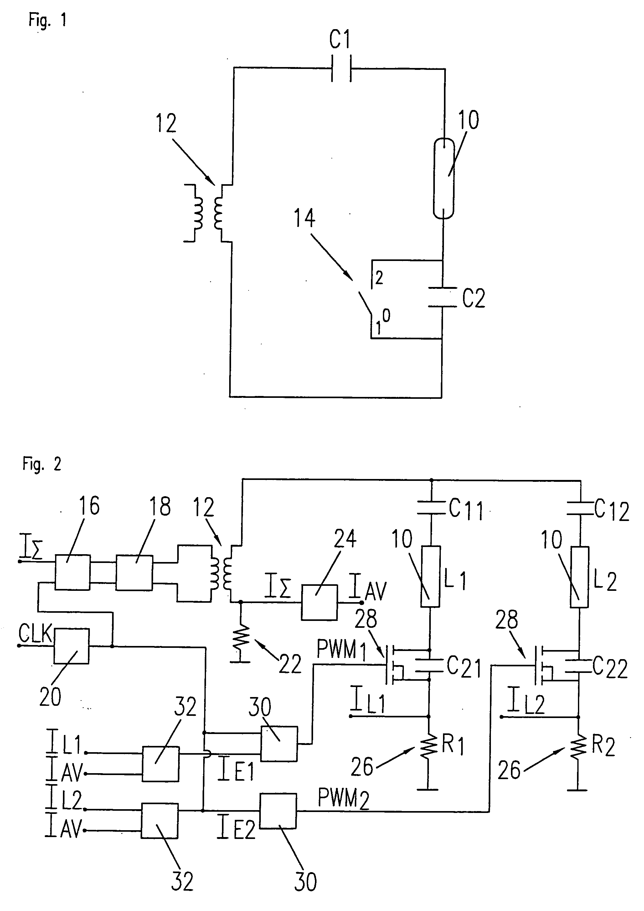
[0029]FIG. 1 shows a circuit diagram to explain the underlying principle of the invention. The circuit comprises a fluorescent lamp 10, particularly a cold cathode fluorescent tube that is fed from a transformer 12 via a capacitive series circuit. The capacitive series circuit comprises two separate capacitors C1, C2 that form a voltage divider. One of these capacitors belonging to the voltage divider is bridged by a switch 14 that is controlled, for example, by pulse width modulation in order to adjust the lamp voltage and thus the lamp current. Linear control of the switch 14 also lies within the range of the invention.
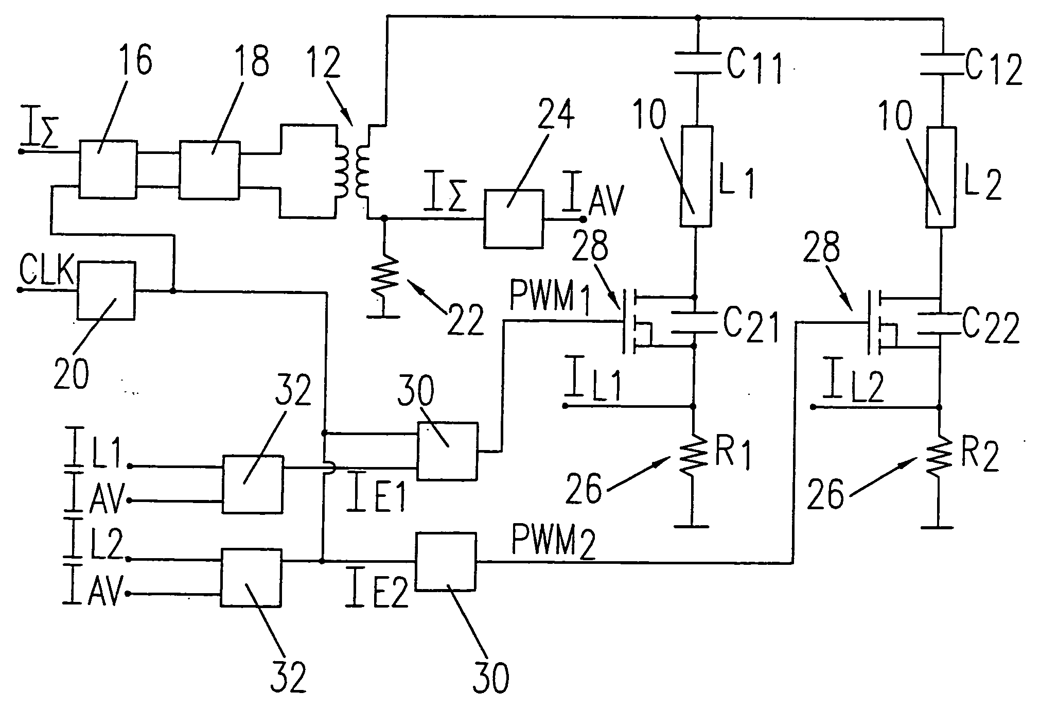
[0030] In the case of a lighting arrangement having a plurality of fluorescent lamps 10, only one transformer 12 having an associated switching stage is needed and only the elements on the secondary side, i.e. the capacitors C1, C2 and the switch 14, have to be provided separately for each of the fluorescent lamps. In practice, the circuit further comprises current...
PUM
 Abstract
Description
Claims
Application Information