Amplifiers

a technology of amplifiers and amplifiers, applied in the field of amplifiers, can solve the problems of undesirable dc offset of the output of the transmitter, reducing the power efficiency of such amplifiers,

Inactive Publication Date: 2006-12-07
UNIV OF BRISTOL
View PDF15 Cites 6 Cited by
  • Summary
  • Abstract
  • Description
  • Claims
  • Application Information

AI Technical Summary

Problems solved by technology

Techniques currently employed in order for sufficient linearity to be obtained drastically reduce the power efficiency

Method used


Image

  • Amplifiers
  • Amplifiers
  • Amplifiers

Examples


first embodiment

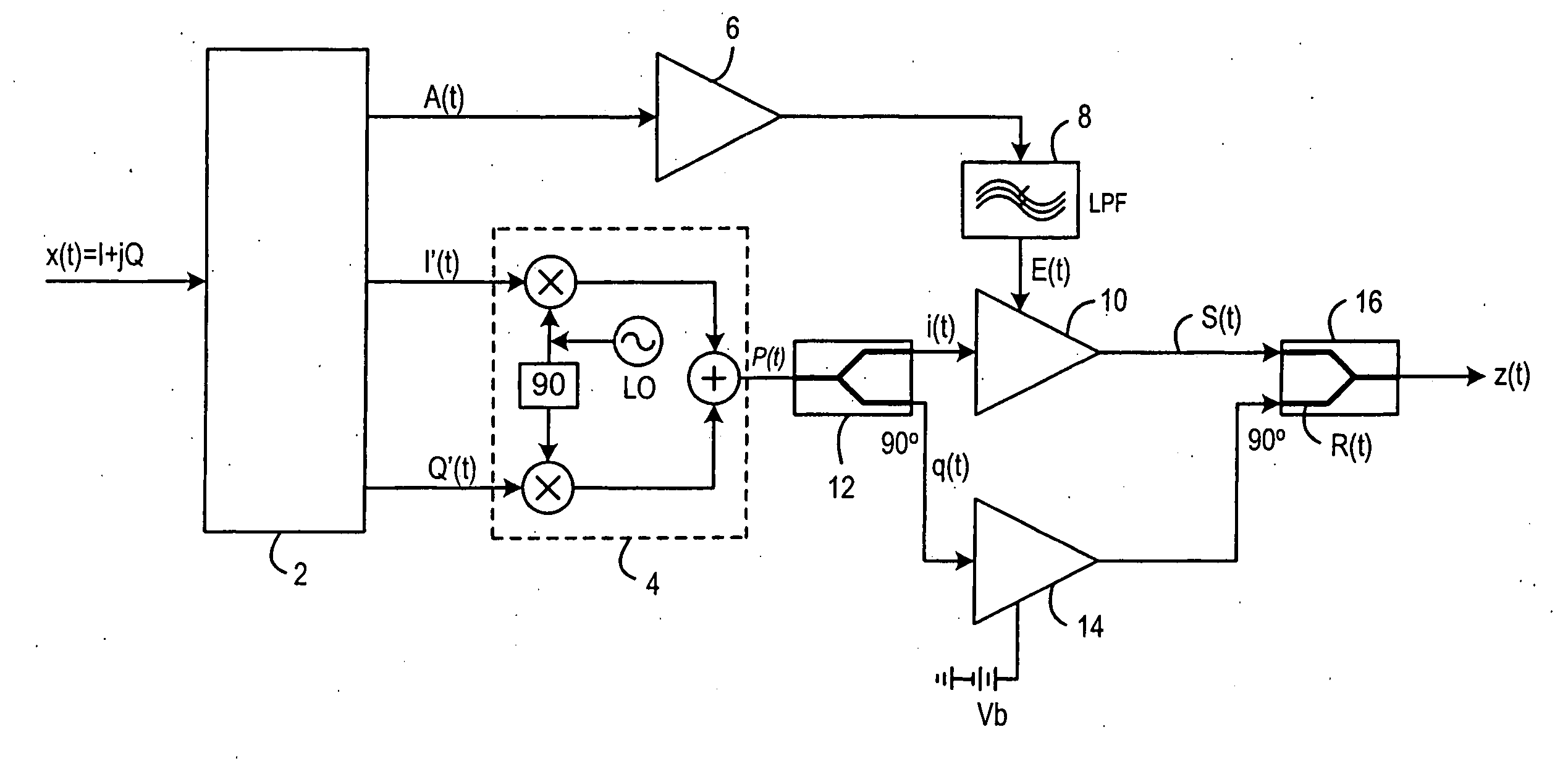
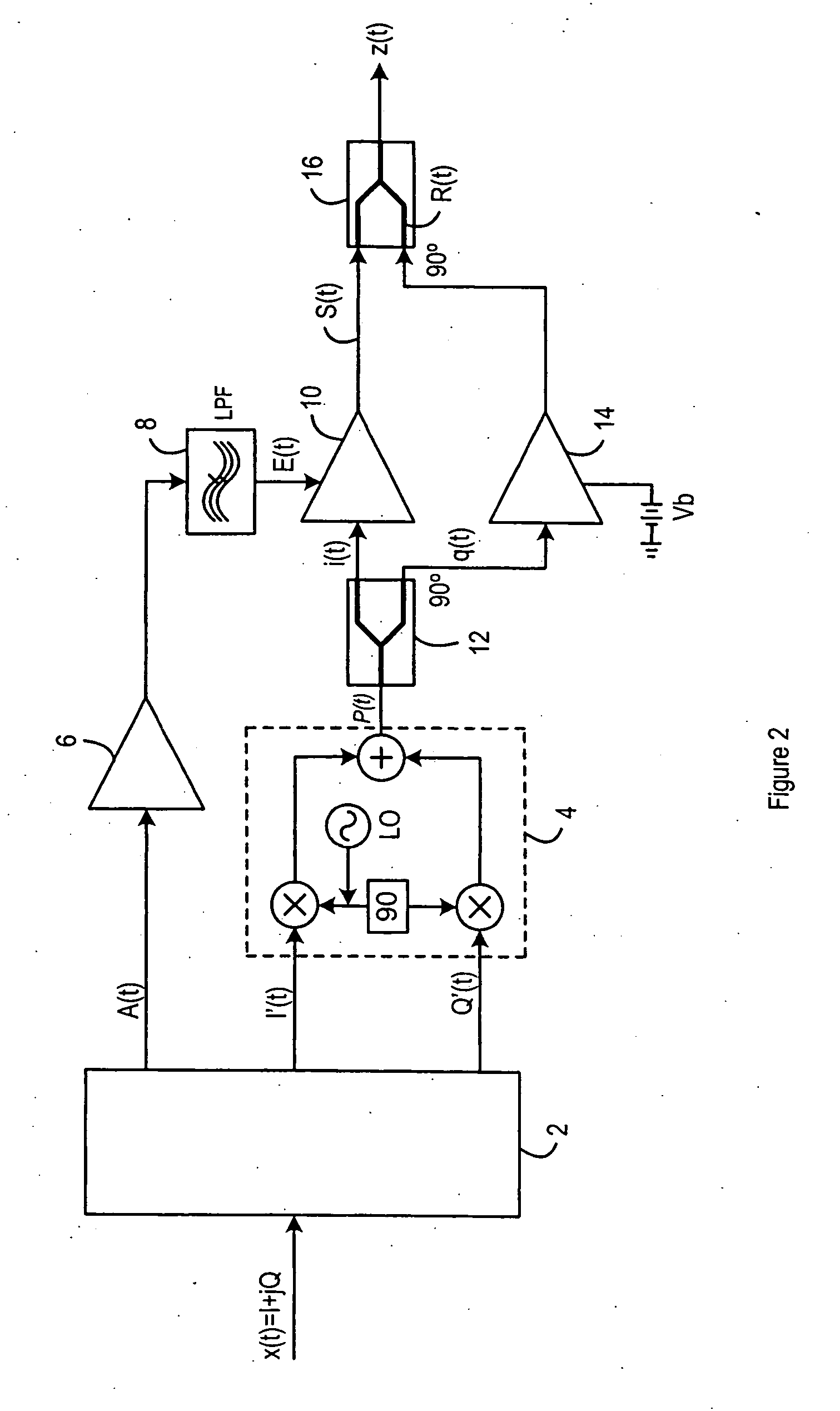
[0018]FIG. 2 illustrates the present invention, which provides an EER transmitter circuit, configured such that the output, z(t), has no DC offset. That is, the output, z(t), is equivalent to the output S(t) of FIG. 1 with no DC offset.

[0019] An input signal, x(t), is input into a signal separation component 2, and converted to an amplitude signal A(t), and Cartesian signals I′(t) and Q′(t), as described in relation to FIG. 1. Again, the signal separation component 2 could be, for example a Digital Signal Processor, or a Field Programmable Gate Array. Within the signal separation component, the amplitude signal A(t) and Cartesian signals I′(t) and Q′(t) are predistorted, as discussed above. The amplitude signal A(t) passes through an envelope modulator 6 and a low pass filter 8. The output from the low pass filter 8 is an envelope signal E(t) which is used to control a first class E amplifier 10, in a manner described with reference to FIG. 1.

[0020] Two class E amplifiers are provi...

second embodiment

[0031] the present invention is shown in FIG. 3. This embodiment differs from the embodiment of FIG. 2 only in the manner of changing the phase of the signal passing through the auxiliary amplifier 14. The phase difference does not have to be generated by the quadrature output of the splitter 12 in combination with the quadrature input of the combiner 16, as it was in the embodiment of FIG. 2. When a standard splitter and a standard combiner are used, with no quadrature inputs or outputs, the 180° phase difference can be introduced by use of at least one phase shifter 22, such that the overall phase shift is the same as that of the embodiment shown in FIG. 2. The requirement is that the signal that passed through the auxiliary amplifier 14 undergoes a total phase shift of 180° with respect to the main amplifier signal. The signal that passed through the main amplifier 10 undergoes no phase shift and therefore has a phase equal to that of the RF phase signal P(t). Signals S(t) and R(...


PUM


Abstract

A class E amplifier circuit comprises a first class E amplifier connected to receive a first signal and operable to amplify the first signal and to output such an amplified first signal and a second class E amplifier connected to receive a second signal related to the first signal, and operable to amplify the second signal and to output such an amplified second signal. The circuit also comprises a combiner having first and second inputs connected to receive amplified signals from the first and second class E amplifiers respectively, and phase shift means operable to introduce a phase shift between signals for combination at the combiner.

Description

CROSS-REFERENCE TO RELATED APPLICATION [0001] This application claims the benefit of the filing date of British Patent Application No. 0509737.3 filed 12 May 2005 in the name of University of Bristol and entitled “Amplifiers”. Amplifiers [0002] The present invention relates to amplifiers, and in particular to class E amplifiers. BACKGROUND [0003] Modulation schemes such as Orthogonal Frequency Division Multiplexing (OFDM) and Wideband Code-Division Multiple Access (W-CDMA) used in telecommunication systems operate with high peak-to-average power ratios. This places a requirement of a large dynamic linearity range for amplifiers used in the associated circuitry. Techniques currently employed in order for sufficient linearity to be obtained drastically reduce the power efficiency of such amplifiers. [0004] One commonly used type of transmitter is the Envelope Elimination and Restoration, EER, transmitter. [0005]FIG. 1 of the accompanying drawings shows a configuration of an EER trans...

Claims


Application Information

Patent Timeline
IPC IPC(8): H03F3/28H03F1/02H03F1/06H03F3/217H03F3/24H04L27/36
CPCH03F1/02H03F1/0205H04L27/361H03F3/217H03F3/24H03F1/0261H03F2200/451H03F1/0222H03F3/2176H04L27/362
Inventor MORRIS, KEVIN
Owner UNIV OF BRISTOL
Why Eureka
Try Eureka