Emergency stop signal device for motor vehicle

a technology for emergency stop signals and motor vehicles, applied in signalling/lighting devices, vehicle components, optical signalling, etc., can solve problems such as false alarms, collision accidents, and false alarms, and achieve the effects of simplifying the control circuit, easy setting, and very precise electronic sensors

Inactive Publication Date: 2006-12-07
QUACH TUAN KIM +2
View PDF16 Cites 42 Cited by
  • Summary
  • Abstract
  • Description
  • Claims
  • Application Information

AI Technical Summary

Benefits of technology

[0011] An advantage of the present invention is that this device is independent from the vehicle's existing electrical signal system and will not interfere with the vehicle's current signal system.
[0012] Another advantage of the present invention is that this device can be used individually and also can be integrated with the vehicle's signal system to flash normal braking signals and tail light.
[0013] And another advantage of the present invention is that the electronic sensor is very precise compared to mechanical sensor and will not be easily triggered by environment factors, such as vibration. It only reflects the speed change.
[0014] A further advantage of the present invention is that the digital circuit simplifies the control circuit. A programmed IC is used which is easily used to set the deceleration value. When the deceleration reaches its preset value, the signal device turns on. It is accurate and has very little delay.
[0015] A yet further advantage of the present invention is that by using an LED Array as the lighting and signal component, its flashing pattern is unique and easily distinguished from ordinary stop lights.
[0016] Another advantage of the present invention is that it is able to display at least three modes of activity, including a normal braking stop, a stationary emergency stop and a panic stop.

Problems solved by technology

If the drivers of rear vehicles can't make a judgment quickly, it may cause a collision accident.
Many factors can trigger the sensor, such as vibration, and thus may trigger false alerts.
Some road conditions may move movable weight in groove, such as when the vehicle moves downhill or uphill, and thus may provide false alerts.

Method used


Image

  • Emergency stop signal device for motor vehicle
  • Emergency stop signal device for motor vehicle
  • Emergency stop signal device for motor vehicle

Examples


Embodiment Construction

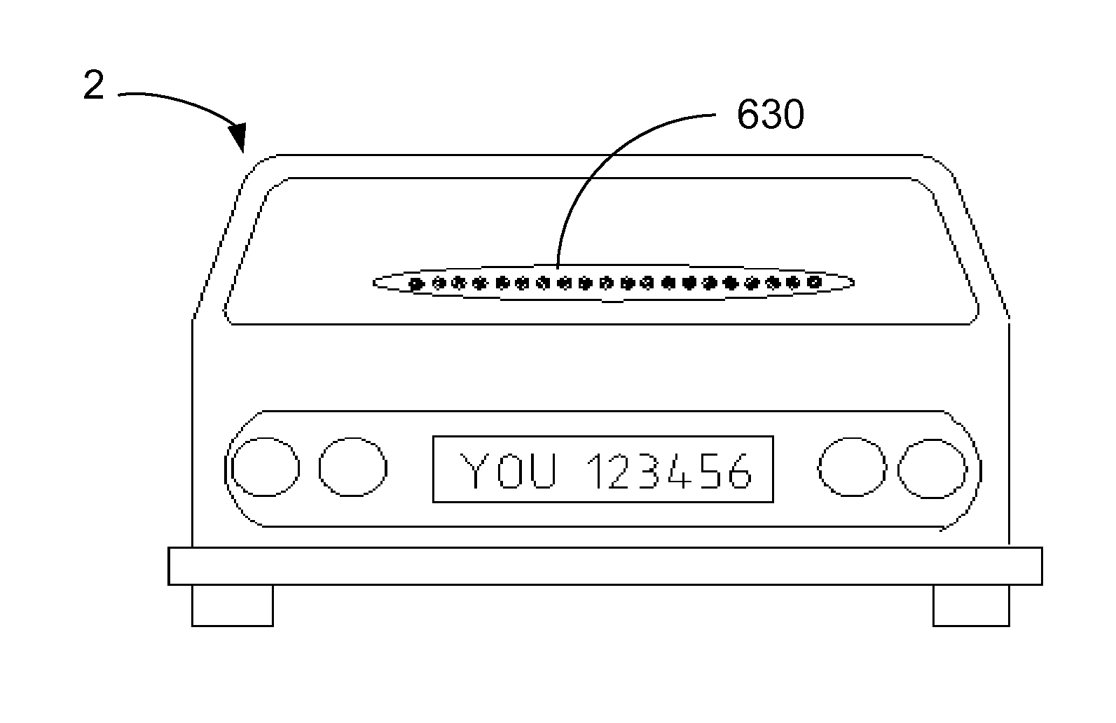
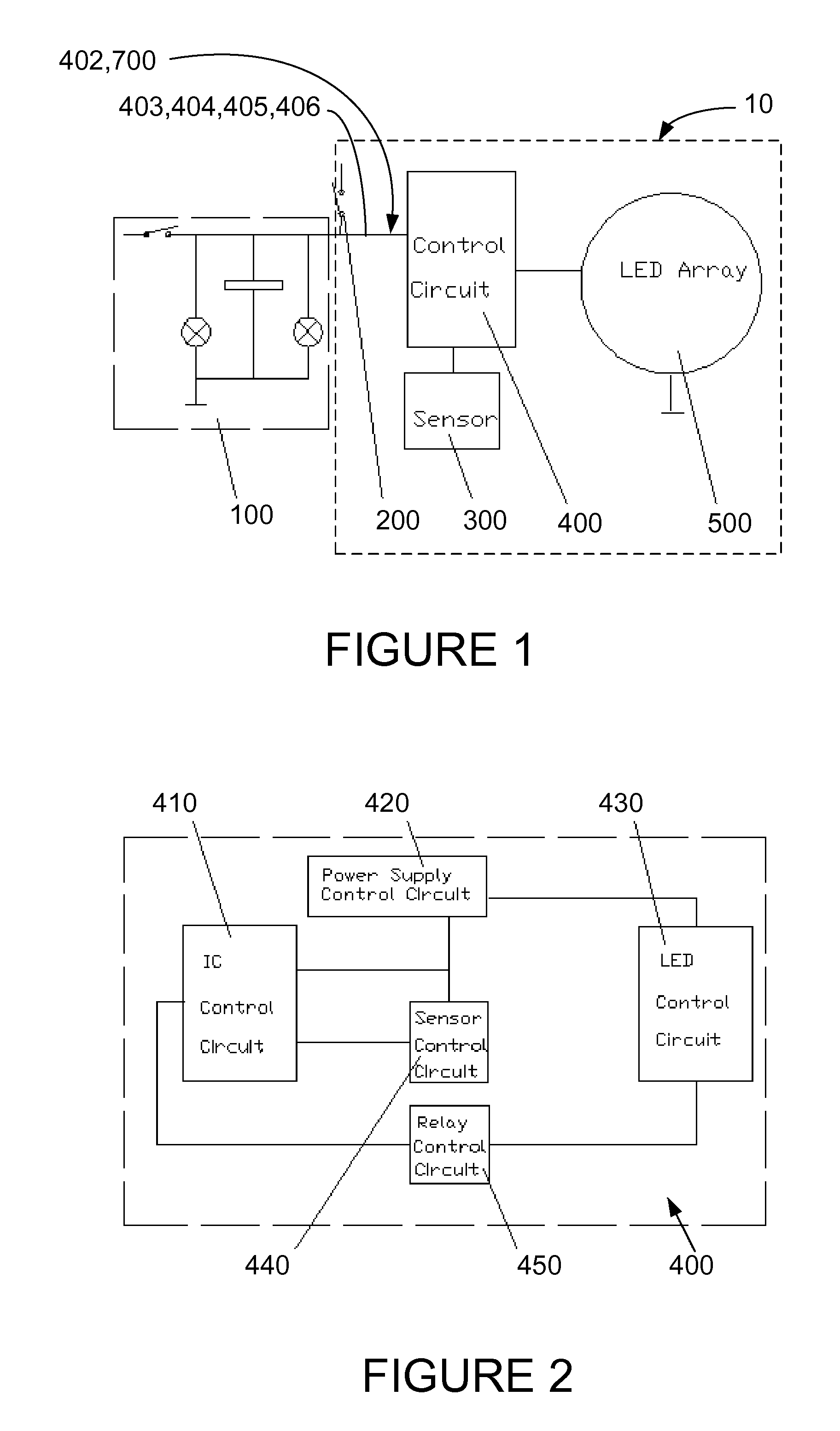
[0033] The present invention is an emergency stop signal device for vehicles, which uses an LED Array to display a series of flashing lights in patterns and colors. The present invention shall be indicated in the following discussion and figures by the designation emergency stop signal device 10. The emergency stop signal device 10 is easily distinguished from normal brake lights and is easily recognized by other drivers as signaling an emergency condition. The emergency stop signal device 10 preferably has multiple modes of activity and turns on brightly when a deceleration sensor has reached a preset value of deceleration. It only reflects the change in acceleration, and not the driver's actions or jolts caused by road conditions, as may prior devices. It warns the driver of following vehicles to keep a safe distance from the user's vehicle in order to avoid rear-end collisions.

[0034] With reference to the drawings, FIG. 1 and FIG. 2, the emergency stop signal device 10 includes ...


PUM


Abstract

An emergency stop signaling device for vehicles is disclosed, including a deceleration sensor which produces deceleration values, an integrated circuit control circuit which receives the deceleration values and produces LED activation control signals. An LED array lights in response to the LED activation control signals from the Integrated Circuit control circuit to produce a light pattern which is distinguishable from an ordinary braking signal. The deceleration sensor is preferably a digital deceleration sensor. The LED array is a flexible LED array, a portable LED array, a linear LED array or a circular LED or a combination of these. The IC control circuit produces signals which activate the LED array to a plurality modes of activity including a tail light mode, a stop light mode, and a panic stop mode.

Description

[0001] The following claims priority from provisional patent application 60 / 677,487, filed May 3, 2005 to the same inventors.TECHNICAL FIELD [0002] The present invention relates generally to the field of signaling devices for motor vehicles, and more particularly to an emergency stop signal for motor vehicles. BACKGROUND OF THE INVENTION [0003] In the prior stop signaling technology, no matter with how much pressure the driver steps on the break pedal and no matter how urgent is the stop, the brightness and color of stoplight is same. There is no specific signal to tell whether the stop is a normal stop or a panic stop. If the drivers of rear vehicles can't make a judgment quickly, it may cause a collision accident. Normally, when driving speed is 60 miles per hour, the driver of rear vehicle should take 2-4 second to observe that the front vehicle is reducing speed. Therefore, to provide a specific emergency stop signal can improve drivers' judgment, so that they make take an early...

Claims


Application Information

Patent Timeline
Patent Type & Authority Applications(United States)
IPC IPC(8): B60Q1/50
CPCB60Q1/444B60Q1/302
Inventor QUACH, TUAN KIMQUACH, TONYGUO, YANXIA
Owner QUACH TUAN KIM
Why Eureka
Try Eureka