Method and apparatus for improving quality of composite video signal and method and apparatus for decoding composite video signal

a composite video signal and video signal technology, applied in the field of methods and apparatus for improving the quality of composite video signals, can solve the problems of undesirable image artifacts, degrade video signals, and difficulty in satisfactorily extracting luminance signals and chrominance signals from composite video signals, and achieve the effect of improving picture quality

Inactive Publication Date: 2006-12-07
SAMSUNG ELECTRONICS CO LTD
View PDF31 Cites 40 Cited by
  • Summary
  • Abstract
  • Description
  • Claims
  • Application Information

AI Technical Summary

Benefits of technology

[0011] The present invention provides a method and apparatus for removing an artifact caused by interference between luminance and chrominance signals of an input composite video signal, ...

Problems solved by technology

Artifacts caused by interference between the luminance and chrominance components can degrade the video signal depending on the performance of the comb filter.
However, crosstalk between the luminance signal and the chrominance signals generates an undesirable image artifact that is not included in the original signal when the composite video signal is transmitted using frequency interleaving.
Thus, it is difficult to satisfactorily extract the luminance signal and the chrominance signals from the composite video signal.
Though a tec...

Method used


Image

  • Method and apparatus for improving quality of composite video signal and method and apparatus for decoding composite video signal
  • Method and apparatus for improving quality of composite video signal and method and apparatus for decoding composite video signal
  • Method and apparatus for improving quality of composite video signal and method and apparatus for decoding composite video signal

Examples


Embodiment Construction

[0041] The present invention will now be described more fully with reference to the accompanying drawings, in which exemplary embodiments of the invention are shown. The invention may, however, be embodied in many different forms and should not be construed as being limited to the embodiments set forth herein; rather, these embodiments are provided so that this disclosure will be thorough and complete, and will fully convey the concept of the invention to those skilled in the art. Throughout the drawings, like reference numerals refer to like elements.

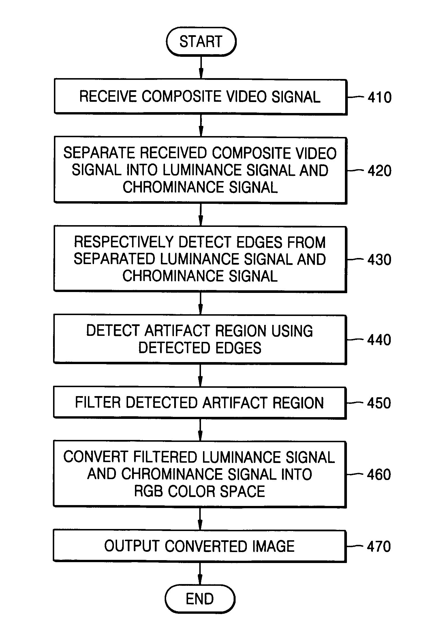
[0042]FIG. 3 is a block diagram of a composite video signal decoder 300 capable of removing an artifact according to the present invention. Referring to FIG. 3, the composite video signal decoder 300 includes a luminance / chrominance signal separator 310, an artifact removing unit 320 and a color space converter 330.

[0043] The luminance / chrominance signal separator 310 separates a luminance signal and a chrominance signal from an inpu...


PUM


Abstract

A method and apparatus for improving the quality of a composite video signal and a method and apparatus for decoding the composite video signal. The method for improving the quality of the composite video signal respectively detects edges from a luminance information signal and a chrominance information signal separated from the composite video signal, detects an artifact region using the detected edges, and filters the detected artifact region. Accordingly, an artifact can be effectively removed while preserving edge information and detail information of an image to improve picture quality.

Description

CROSS-REFERENCE TO RELATED PATENT APPLICATION [0001] This application claims the benefit of Korean Patent Application No. 10-2005-0048115, filed on Jun. 4, 2005, in the Korean Intellectual Property Office, the disclosure of which is incorporated herein in its entirety by reference. BACKGROUND OF THE INVENTION [0002] 1. Field of the Invention [0003] Methods and apparatuses consistent with the present invention relate to removing artifacts generated when a luminance signal and a chrominance signal are extracted from a composite video signal to improve picture quality and decoding the composite video signal. [0004] 2. Description of the Related Art [0005] In general, a color TV video signal includes a luminance component and a chrominance component modulated within a restricted bandwidth. The luminance and chrominance components are separated from each other using a comb filter and decoded to be restored to the image corresponding to the color TV video signal. Artifacts caused by inter...

Claims


Application Information

Patent Timeline
IPC IPC(8): H04N5/00
CPCH04N9/646H04N11/146H04N9/67H04N9/66H04N5/21
Inventor KIM, SUNG-HEE
Owner SAMSUNG ELECTRONICS CO LTD
Why Eureka
Try Eureka