Step-and-shoot cardiac CT imaging

a ct imaging and step-and-shoot technology, applied in the field of diagnostic imaging, can solve the problems of organ failure, sudden death, organ failure,

Active Publication Date: 2006-12-07
GENERAL ELECTRIC CO
View PDF4 Cites 30 Cited by
  • Summary
  • Abstract
  • Description
  • Claims
  • Application Information

AI Technical Summary

Problems solved by technology

The narrowing or constriction of vessels carrying blood to the heart is a well-known cause of heart attacks and, gone untreated, can lead to sudden death.
In general, narrowing of blood-carrying vessels supplying an organ will ultimately lead to compromised function of the organ in question, at best, and organ failure, at worst.
If the combination of gantry speed and helical pitch is not properly selected, the entire heart volume will not be uniformly covered in the reconstructed images.
Although small gaps could be filled by image space interp

Method used


Image

  • Step-and-shoot cardiac CT imaging
  • Step-and-shoot cardiac CT imaging
  • Step-and-shoot cardiac CT imaging

Examples


Embodiment Construction

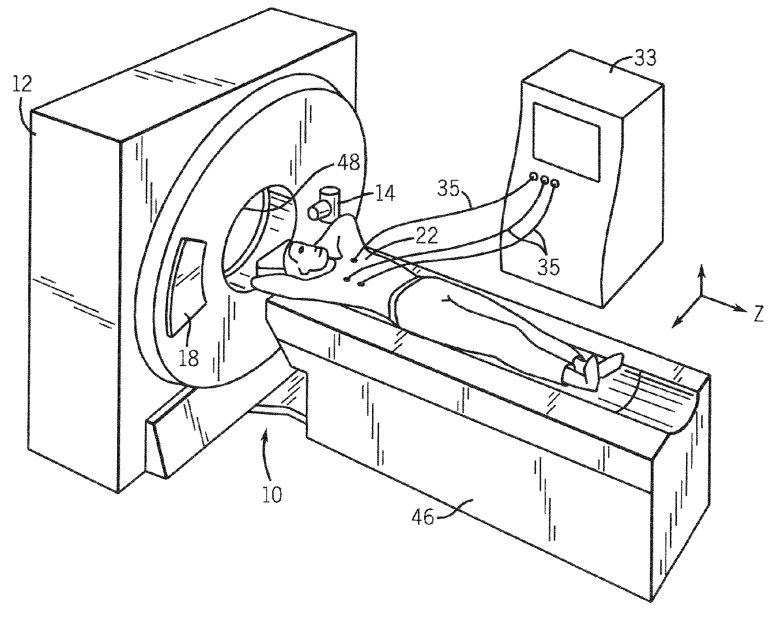
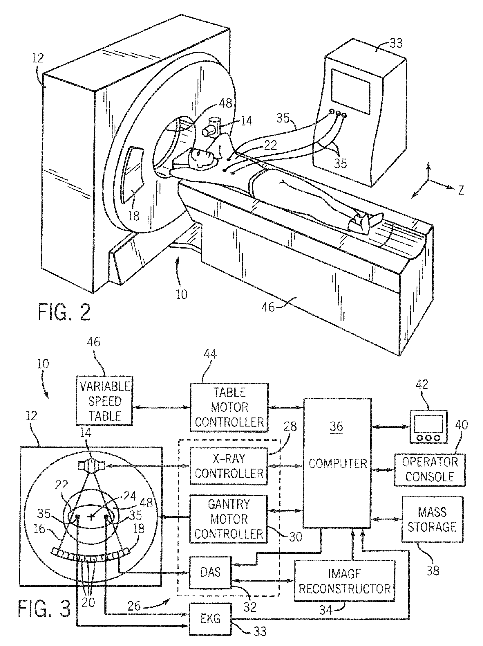
[0030] Referring to FIGS. 2 and 3, a computed tomography (CT) imaging system 10 is shown as including a gantry 12 having an x-ray source 14 that projects a beam of x-rays 16 toward a detector array 18 on the opposite side of the gantry 12. Detector array 18 is formed by a plurality of detectors 20 that sense the projected x-rays that pass through a medical patient 22. In a preferred embodiment, detector array 18 has 64 rows of detectors for the acquisition of 64 slices of data in a single gantry rotation. Each detector 20 produces an electrical signal that represents the intensity of an impinging x-ray beam and hence the attenuated beam as it passes through the patient 22. During a scan to acquire x-ray projection data, gantry 12 and the components mounted thereon rotate about a center of rotation 24.

[0031] Rotation of gantry 12 and the operation of x-ray source 14 are governed by a control mechanism 26 of CT system 10. Control mechanism 26 includes an x-ray controller 28 that prov...


PUM


Abstract

The present invention is directed to a method and system of controlling rotation of a gantry to rotate at a rotational speed such that a desired relationship between center projection angles of neighboring partial scans is maintained.

Description

BACKGROUND OF THE INVENTION [0001] The present invention relates generally to diagnostic imaging and, more particularly, to a method and apparatus of cardiac CT imaging with discontinuous table translation. The invention further relates to the incremental translation of a subject during CT data acquisition such that the subject is not translated to a next scan position until valid data is acquired for a current scan position. Additionally, the present invention is directed to a method and system of controlling the rotational speed of the gantry of a CT scanner during physiologically gated, step-and-shoot CT data acquisition such that the projection angle of a current half-scan and its neighboring half-scans differ within a desired range. In this regard, the present invention maintains data integrity during cardiac irregularities. [0002] The narrowing or constriction of vessels carrying blood to the heart is a well-known cause of heart attacks and, gone untreated, can lead to sudden ...

Claims


Application Information

Patent Timeline
IPC IPC(8): A61B6/00G01N23/00G21K1/12H05G1/60
CPCA61B6/0457A61B6/027A61B6/541A61B6/503A61B6/0487
Inventor HSIEH, JIANGLI, JIANYINGLONDT, JOHN H.VASS, MELISSAOKERLUND, DARIN R.HOPPEL, BERNICE
Owner GENERAL ELECTRIC CO
Why Eureka
Try Eureka