Blade of axial flow-type rotary fluid machine

a rotary fluid machine and blade technology, applied in the direction of marine propulsion, vessel construction, other chemical processes, etc., can solve the problems of increasing blade pressure loss and insufficient reduction of pressure loss accompanying secondary flow, and achieve the effect of reducing the curvature of the second bent portion

Inactive Publication Date: 2006-12-07
HONDA MOTOR CO LTD
View PDF4 Cites 23 Cited by
  • Summary
  • Abstract
  • Description
  • Claims
  • Application Information

AI Technical Summary

Benefits of technology

[0007] The present invention has been accomplished with the above circumstance in view, and it is an object of the present invention to decrease the pressure loss in a blade of an axial-flow rotary fluid machine used mainly in a transonic range.
[0011] With the above arrangement, the front first bent portion bent toward the intrados and the rear second bent portion bent toward the extrados are provided on the camber line on the trailing edge of the blade of the axial-flow rotary fluid machine, and the curvature of the second bent portion is decreased from the side of the blade root toward the blade tip. Therefore, a higher-pressure portion on the intrados which is a pressure surface of the blade is displaced toward the trailing edge, so that a secondary flow from the side of the blade tip toward the blade root can be suppressed, whereby a pressure loss particularly in the vicinity of the blade root can be suppressed to the minimum.

Problems solved by technology

A turbine blade having a low aspect ratio has a significant tendency (a secondary flow) that the flow of a fluid along a blade surface is deflected from the side of a blade tip toward a blade root, resulting in a problem of an increased pressure loss in the blade.
In the above-described conventional blade, however, a three-dimensional shape of the turbine blade, namely, a difference between the airfoil of the blade root and the airfoil of the blade tip is not taken into consideration, so that the pressure loss accompanying the secondary flow cannot be sufficiently decreased.

Method used


Image

  • Blade of axial flow-type rotary fluid machine
  • Blade of axial flow-type rotary fluid machine
  • Blade of axial flow-type rotary fluid machine

Examples


Embodiment Construction

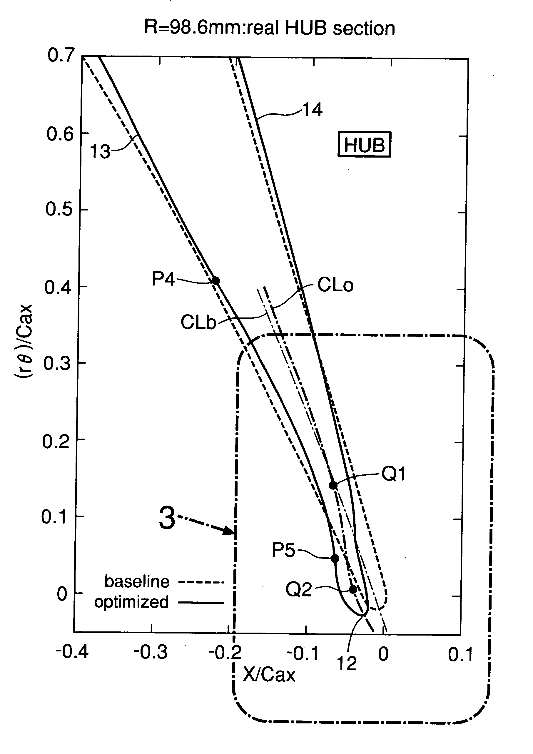
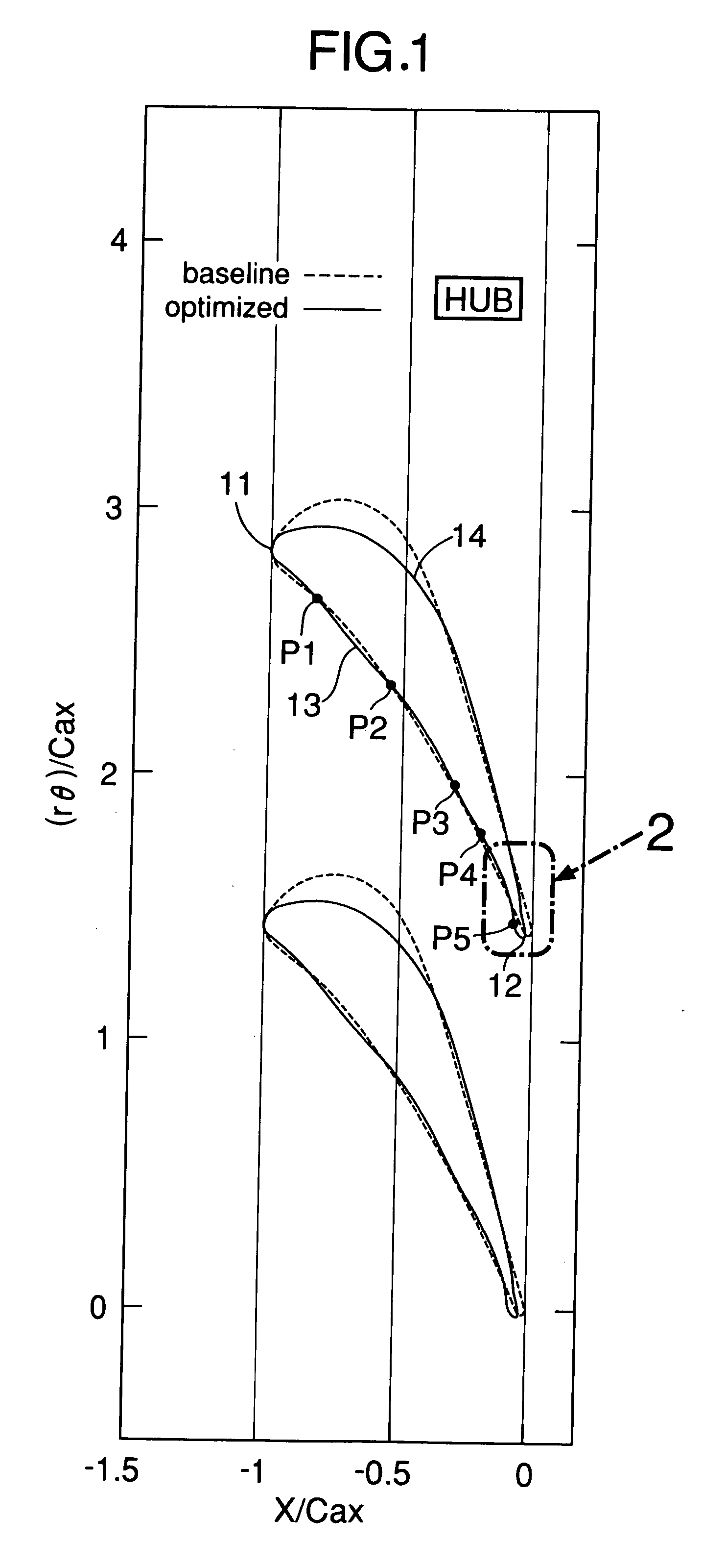
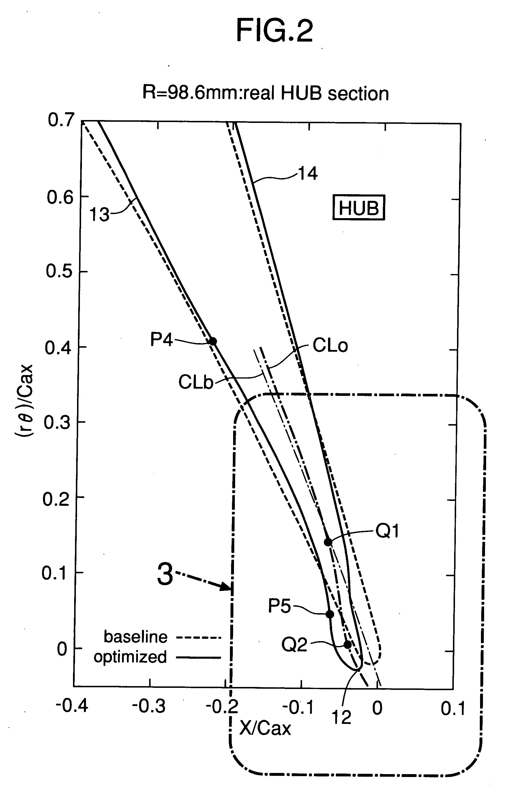
[0026] Turbine blades according to the present embodiment are disposed in an annular gas passage in an axial-flow turbine to constitute a turbine blade cascade. An airfoil shown in FIG. 1 is of a blade root (a portion connected to a hub) at a radial inner end of a turbine stator blade, and an airfoil shown in FIG. 4 is of a blade tip at a radial outer end of the turbine stator blade. The airfoil of the turbine blade is changed progressively from the blade root toward the blade tip. As apparent from FIG. 7B, the three-dimensional shape of the turbine blade has an ultra-low aspect ratio with a span length longer than a chord length.

[0027] In the airfoil of the blade root shown in FIG. 1, a broken line shows an airfoil (a baseline) in a comparative example, which is a basis, and a solid line shows an airfoil (optimized) in the embodiment, which is optimized on the basis of the comparative example. The airfoil in the embodiment includes an intrados 13 (a positive pressure surface) adap...


PUM


Abstract

A first bent portion bent toward an intrados and a second bent portion located in the rear of the first bent portion and bent toward an extrados are provided on a camber line on a trailing edge in the rear of 90% of a chord length of a turbine blade having an extremely low aspect ratio for an axial-flow turbine. The inclination of the camber line immediately in the rear of the second bent portion on the side of a blade root is substantially equal to the inclination of the camber line immediately in front of the first bent portion, and the curvature of the second bent portion is decreased from the side of the blade root toward a blade tip. As a result, a higher-pressure portion on the intrados which is a pressure surface of the turbine blade is displaced toward the trailing edge, and thus a secondary flow from the side of the blade tip toward the blade root can be suppressed, whereby a pressure loss particularly in the vicinity of the blade root can be suppressed to the minimum.

Description

RELATED APPLICATION DATA [0001] German priority application No. 10 2005 025 213.3, upon which the present application is based, is hereby incorporated in its entirety herein by reference. BACKGROUND OF THE INVENTION [0002] 1. Field of the Invention [0003] The present invention relates to a three-dimensional shape of a blade used in an axial-flow rotary fluid machine such as an axial-flow turbine and an axial-flow compressor, and particularly to a blade having an extremely small aspect ratio. [0004] 2. Description of the Related Art [0005] An airfoil of a turbine blade of an axial-flow turbine described in Japanese Patent Application Laid-open No. 2002-138801 includes an inflection point between an upstream concave portion and a downstream convex portion in the rear of a 80% position on an intrados, so that a shock wave generated from the intrados of a trailing edge is dispersed into two components by the effect of the inflection point to weaken the respective shock wave components, ...

Claims


Application Information

Patent Timeline
Patent Type & Authority Applications(United States)
IPC IPC(8): B64C11/16
CPCF01D5/141Y10S416/05Y10S416/02Y02T50/673Y02T50/60
Inventor HASENJAGER, MARTINASENDHOFF, BERNHARDSONODA, TOYOTAKAARIMA, TOSHIYUKI
Owner HONDA MOTOR CO LTD
Why Eureka
Try Eureka