Flow control through plural, parallel connecting channels to/from a manifold

Inactive Publication Date: 2006-12-07
VELOCYS CORPORATION
View PDF21 Cites 72 Cited by
  • Summary
  • Abstract
  • Description
  • Claims
  • Application Information

AI Technical Summary

Benefits of technology

[0031] A “gate” comprises an interface between the manifold and two or more connecting channels. A gate has a nonzero volume. A gate controls flow into multiple connecting channels by varying the cross sectional area of the entrance to the connecting channels. A gate is distinct from a simple orifice, in that the fluid flowing through a gate has positive momentum in both the direction of the flow in the manifold and the direction of flow in the connecting channel as it passes through the gate. In contrast, greater than 75% of the positive momentum vector of flow through an orifice is in the direction of the orifice's axis. A typical ratio of the cross sectional area of flow through a gate ranges between 2-98% (and in some embodiments 5% to 52%) of the cross sectional area...

Problems solved by technology

Flow passing though the inlet passes into the manifold and momentum tends to force greater flow through the second connecting channel; howe...

Method used


Image

  • Flow control through plural, parallel connecting channels to/from a manifold
  • Flow control through plural, parallel connecting channels to/from a manifold
  • Flow control through plural, parallel connecting channels to/from a manifold

Examples


example

Modeling of Flow in a z-Manifold

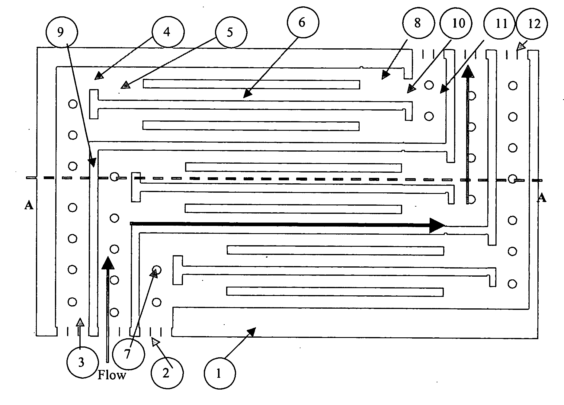
[0116] The new gate design was modeled in a z-manifold in with the header gate of a single gate system. This system was modeled in computational fluid dynamics using the code Fluent 6.2.16. It is made from two solid laminates, laminate 1 of 0.025 cm (0.010″) thickness and laminate 2 of 0.046 cm (0.018″) flanked by two walls. The model system consists of the following flow paths:

[0117] 1. A M2M manifold that is 1.270 cm (0.500″) in width, 0.071 (0.028″) tall gap and 3.353 cm (1.320″) length. The length of the M2M manifold upstream of the header gate is 2.083 cm (0.820″) and 0.406 cm (0.160″) downstream of the header gate that ends the header M2M manifold. The M2M manifold is made up of laminates 1 and 2. The inlet has a constant mass flow rate inlet condition. The LM2M is 2.083 cm.

[0118] 2. A header gate that is 0.046 cm tall, 1.270 cm (0.500″) wide and 0.152 cm (0.060″) long, in laminate 2.

[0119] 3. The first section, or flow straightener, of leng...


PUM


Abstract

The invention provides apparatuses and techniques for controlling flow between a manifold and two or more connecting microchannels. Flow between plural connecting microchannels, that share a common manifold, can be made more uniform by the use of flow straighteners and distributors that equalize flow in connecting channels. Alternatively, flow can be made more uniform by sections of narrowed diameter within the channels. Methods of making apparatus and methods of conducting unit operations in connecting channels are also described.

Description

RELATED APPLICATIONS [0001] In accordance with 35 U.S.C. sect. 119(e), this application claims priority to U.S. Provisional Application No. 60 / 669,640 filed 8 Apr. 2005.FIELD OF THE INVENTION [0002] This invention relates to flow through manifolds and connecting channels. INTRODUCTION [0003] There has been significant interest in controlling flow in plural, parallel channels that connect to a manifold. Specifically, there has been a problem with nonuniform flow in the connecting channels leading to device inefficiencies. Detailed solutions to this problem can be found in U.S. Published Patent Application No. 2005 / 0087767 by Fitzgerald et al., which is incorporated herein as if reproduced in full below. [0004] A less effective design has been described by Golbig et al., in U.S. Patent Application Publication 2002 / 0106311 which described plate microreactor designs in which the widths of connecting channels are varied in order to provide equalized residence time of fluids in the channe...

Claims


Application Information

Patent Timeline
IPC IPC(8): B01J19/00H01L31/00B01L3/02
CPCB01J19/0093F28F2260/02B01J2219/00822B01J2219/00824B01J2219/00833B01J2219/00835B01J2219/0086B01J2219/00889B01J2219/00891B01J2219/00995B01L3/502746B01L2200/027B01L2300/0864B01L2300/0887B01L2400/0487B01L2400/086F28F13/06B01J2219/00783Y10T137/0396
Inventor TONKOVICH, ANNA LEEYANG, BINPERRY, STEVEN T.FITZGERALD, SEAN P.ARORA, RAVILUZENSKI, ROBERTYUSCHAK, THOMAS D.
Owner VELOCYS CORPORATION
Why Eureka
Try Eureka