Methods and devices for mapping the ventricle for pacing lead placement and therapy delivery

a technology of ventricle and pacing leads, applied in the field of biventricular pacing, can solve problems such as optimal placement, and achieve the effects of optimizing heart function, improving placement of pacing leads, and measuring the effectiveness of pacing from the location

Inactive Publication Date: 2006-12-07
STEREOTAXIS
View PDF97 Cites 94 Cited by
  • Summary
  • Abstract
  • Description
  • Claims
  • Application Information

AI Technical Summary

Benefits of technology

[0004] Some embodiments of the method of this invention provide for improved placement of pacing leads in the heart, and in particular in the ventricles. The embodiments employ an advanced device and technique for the interrogation and testing of potential pacing locations to optimize heart function. Generally, a method of placing pacing leads in accordance with this invention comprises moving an electrode catheter successively to a plurality of possible placement sites in the heart. At each site a determination is made whether the tissue at the site is viable. If the tissue at the site is viable, a pacing signal is applied to the tissue at the site, and the effectiveness of pacing from the location is measured. This is repeated over a region of the heart until one or more locations of optimum pacing are determined. The pacing lead can then be placed in the optimum location identified.
[0005] Thus, methods in accordance with the preferred embodiments of the present invention facilitate the placement of pacing leads, and in at least some embodiments permit placement of pacing leads at better locations than current methods of lead placement, which merely seek functional locations. These and other features and advantages will be in part apparent and in part pointed out hereinafter.

Problems solved by technology

While this results in a functional placement, it does not result in the optimal placement of the leads.

Method used


Image

  • Methods and devices for mapping the ventricle for pacing lead placement and therapy delivery
  • Methods and devices for mapping the ventricle for pacing lead placement and therapy delivery
  • Methods and devices for mapping the ventricle for pacing lead placement and therapy delivery

Examples


first embodiment

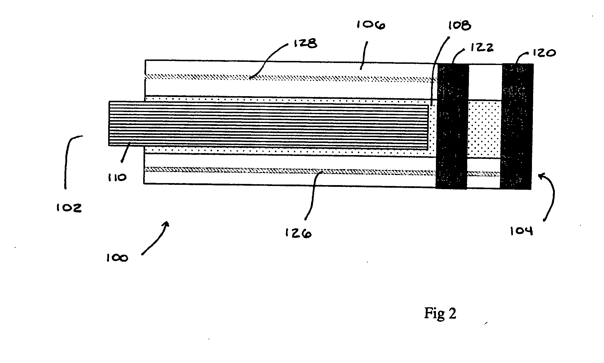
[0032] a device useful in at least some of the preferred embodiments of the methods of this invention is indicated generally as 100 in FIG. 2. The device 100 has a proximal end 102, a distal end 104, and a sidewall 106 forming lumen 108 extending therebetween. In the preferred embodiment the lumen 108 is adapted to receive and pass a guide wire 110 for facilitating the navigation of the device 100. There are preferably two ring electrodes 120 and 122 on the distal end of 104 of the device. The electrodes 120 and 122 may be positioned at the distal end of the device 100. The electrode 122 is positioned proximal to, and spaced from, the electrode 120. Conductors 126 and 128 extend from the electrodes 120 and 122, respectively through the wall 106 of the device 100 to the proximal end where they can be connected to suitable equipment for sensing signals between the electrodes 120 and 122 and for applying a pacing signal between the electrodes 120 and 122.

[0033] The guide wire 110 can b...

second embodiment

[0034] a device useful in at least some of the preferred embodiments of the methods this invention is indicated generally as 150 in FIG. 3. The device 150 has a proximal end 152, a distal end 154, and a sidewall 156 forming lumen 158 extending therebetween. In the preferred embodiment the lumen 158 is adapted to receive and pass a guide wire 160 for facilitating the navigation of the device 150. The guide wire 160 can have one or more magnetically responsive elements 162 thereon. These elements 162 can be made from a permanent magnetic material or a permeable magnetic material of sufficient size and shape that it tends to align the distal end of the guide wire 160 relative to an externally applied magnetic field. There are preferably two ring electrodes 170 and 172 on the distal end of 154 of the device 150. The electrode 170 may be positioned at the distal end of the device 150. The electrode 172 is positioned proximal to, and spaced from, the electrode 170. Conductors 176 and 178 ...

third embodiment

[0036] a device useful in at least some of the preferred embodiments of the methods this invention is indicated generally as 200 in FIGS. 4 and 5. The device 200 has a proximal end 202, a distal end 204, and a sidewall 206 forming lumen 208 extending from the proximal end to a point proximal to the distal end 204. In the preferred embodiment the lumen 208 is adapted to receive a guide wire 210 for facilitating the navigation of the device 200, the guide wire 210 can function to engage and push the distal end of the device 200. In addition, or alternatively, the guide wire 210 may function to stiffen at least the distal portion of the device 200. The guide wire 210 can optionally have one or more magnetically responsive elements (not shown) thereon. These elements can be made from a permanent magnetic material or a permeable magnetic material of sufficient size and shape that it tends to align the distal end of the guide wire 210 relative to an externally applied magnetic field. Thus...


PUM


Abstract

A method of placing a pacing lead in the heart includes moving an electrode catheter successively to a plurality of possible placement sites. The viability of the tissue at each site is determined. If the tissue at the site is viable, a pacing signal is applied to the tissue at the site, and the effectiveness of the pacing from the site is measured. After the area has been mapped in this fashion, at least one pacing lead is placed from at least one of the sites which exceeded a predetermined level of pacing effectiveness.

Description

CROSS-REFERENCE TO RELATED APPLICATIONS [0001] This application is a continuation of U.S. patent application Ser. No. 11 / 445,921, filed Jun. 2, 2006, which claims the benefit of U.S. Provisional Patent Application Ser. No. 60 / 686,785, filed Jul. 25, 2005, the entire disclosure of which is incorporated herein by reference.BACKGROUND OF THE INVENTION [0002] This invention relates to bi-ventricular pacing, and in particular to the placement of pacing leads for bi-ventricular pacing. [0003] Bi-Ventricular pacing has been shown to improve cardiac function in heart failure patients with ventricular de-synchrony by pacing both ventricles using right ventricular and left ventricular pacing leads in such a fashion as to improve hemodynamic function. Typically the leads are individually positioned in the ventricle, and tested to determine whether pacing from that location is acceptable, and if so, the lead is left in place. While this results in a functional placement, it does not result in t...

Claims


Application Information

Patent Timeline
Patent Type & Authority Applications(United States)
IPC IPC(8): A61N1/04
CPCA61B18/1492A61B2018/00351A61B2018/00839A61N1/3684A61N1/3627A61N1/368A61N1/3622A61N1/36843A61N1/36842
Inventor VISWANATHAN, RAJU R.
Owner STEREOTAXIS
Why Eureka
Try Eureka