Vacuum cleaner

a vacuum cleaner and vacuum cleaner technology, applied in the field of vacuum cleaners, can solve the problems of cumbersome separation of dust collecting filter from the cleaner body for periodic washing or replacement, and user-intensive effor

Inactive Publication Date: 2006-12-14
LG ELECTRONICS INC
View PDF8 Cites 38 Cited by
  • Summary
  • Abstract
  • Description
  • Claims
  • Application Information

AI Technical Summary

Benefits of technology

[0019] To achieve these objects and other advantages and in accordance with the purpose of the invention, as embodied and broadly described herein, a vacuum cleaner includes a cleaner body having a body suction opening, and a fan-motor assembly for forced circulation of air introduced through the body suction opening, a dust collecting device in communication with the body suction opening, the dust collecting device having a main cyclone unit for separating foreign matters from the air introduced thereto by a cyclone principle, and at least one supplementary cyclone unit around the main cyclone for separating foreign matters from the air discharged from the main cyclone unit, a suction unit having an air suction opening in communication with the body suction opening, for drawing external air through the air suction opening, and a filter assembly having a dust collecting filter in a flow passage through which the air from the supplementary cyclone unit flows for separating the foreign matters from the air, and a filter housing in the dust collecting device or the cleaner body for hous

Problems solved by technology

However, the related art dust collecting device has a problem in that the separation of the dust collecting filter from the cleaner body for periodic washing or replacement is cumbersome.
Moreover,

Method used


Image

  • Vacuum cleaner
  • Vacuum cleaner
  • Vacuum cleaner

Examples


Embodiment Construction

[0033] Reference will now be made in detail to the preferred embodiments of the present invention, examples of which are illustrated in the accompanying drawings. Wherever possible, the same reference numbers will be used throughout the drawings to refer to the same or like parts.

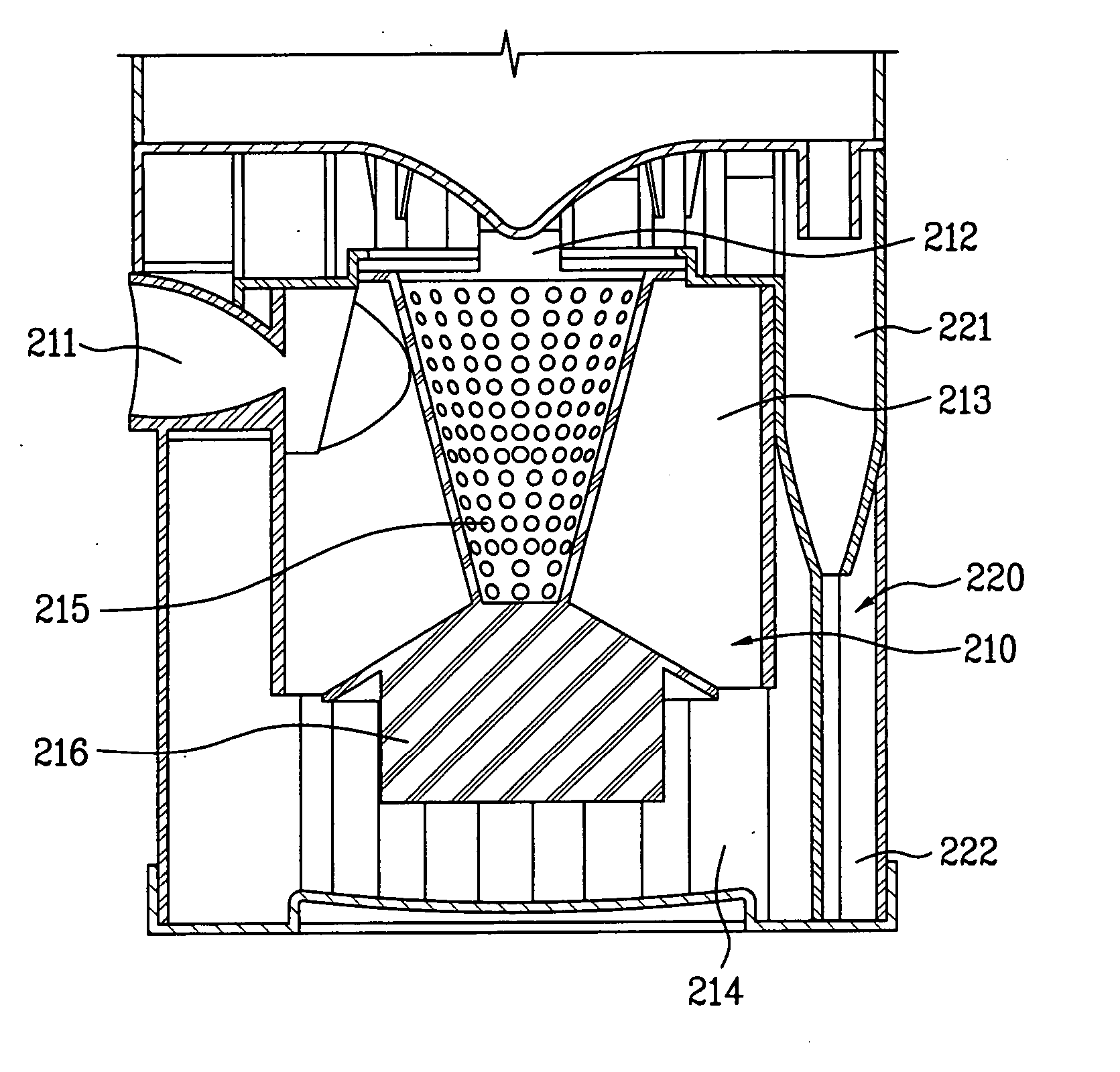
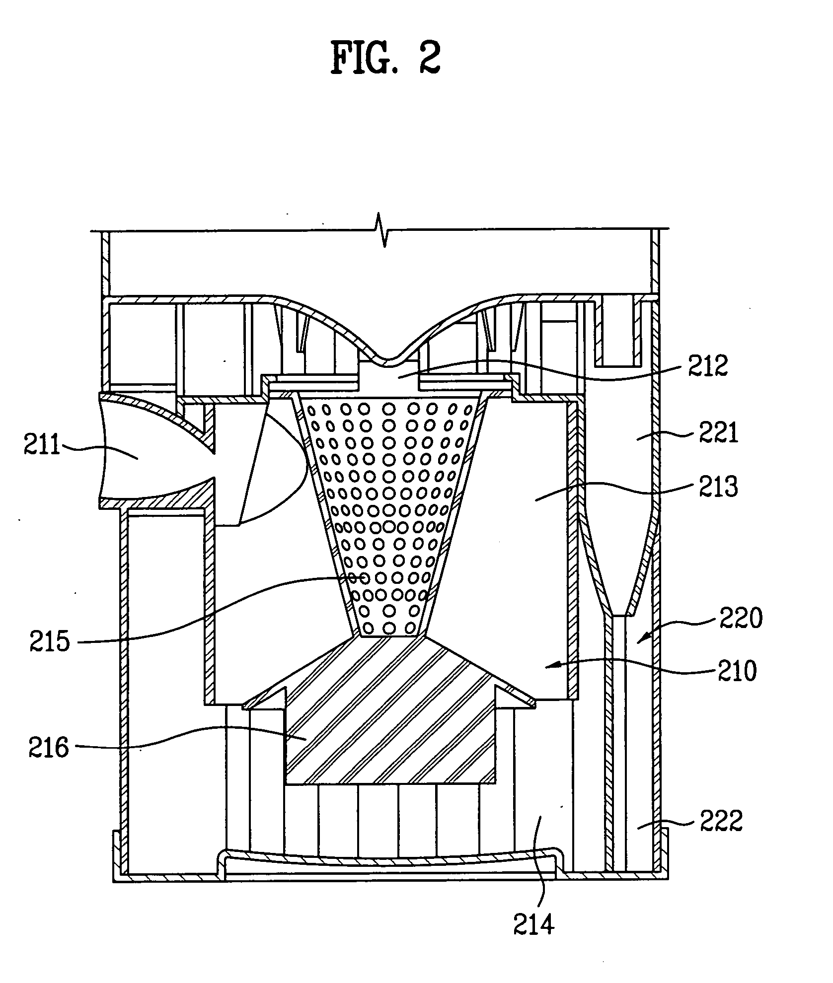
[0034] A system and an operation principle of a cyclone dust collecting device in a vacuum cleaner will be described with reference to FIG. 2.

[0035] A cleaner is provided with a dust collecting device. In the dust collecting devices, there are a system using a general dust bag and a cyclone system.

[0036] Recently, the cyclone system is used, in which no replacement of the dust bag is required, wherein a cyclone principle is used for collecting foreign matters, such as dust, from air. In order to improve a dust collecting performance, a multiple cyclone dust collecting device having a plurality of cyclone units mounted thereto is used.

[0037] The multiple cyclone dust collecting device includes a main cyc...


PUM


Abstract

An object of the present invention is to provide a dust collecting device in a vacuum cleaner replacement of which dust collecting filter is easy. To achieve this, the present invention provides a vacuum cleaner including a cleaner body having a body suction opening, and a fan-motor assembly for forced circulation of air introduced through the body suction opening, a dust collecting device in communication with the body suction opening, the dust collecting device having a main cyclone unit for separating foreign matters from the air introduced thereto by a cyclone principle, and at least one supplementary cyclone unit around the main cyclone for separating foreign matters from the air discharged from the main cyclone unit, a suction unit having an air suction opening in communication with the body suction opening, for drawing external air through the air suction opening, and a filter assembly having a dust collecting filter in a flow passage through which the air from the supplementary cyclone unit flows for separating the foreign matters from the air, and a filter housing in the dust collecting device for housing the dust collecting filter therein and drawing out of the dust collecting device assembly in a sliding fashion, thereby permitting easy mounting/dismounting of the dust collecting filter on/off the dust collecting device, enabling convenient washing or replacement of the dust collecting filter.

Description

CROSS-REFERENCE TO RELATED APPLICATIONS [0001] This application claims the benefit of Korean Application No. P2005-0049801, filed on Jun. 10, 2005, which is hereby incorporated by reference as if fully set forth herein. BACKGROUND OF THE INVENTION [0002] 1. Field of the Invention [0003] The present invention relates to vacuum cleaners, and more particularly, to a vacuum cleaner mounting / dismounting of a dust collecting filter on / off which is easy. [0004] 2. Discussion of the Related Art [0005] A dust collecting device in a related art vacuum cleaner will be described with reference to FIG. 1. [0006] In the vacuum cleaners, in general, there are canister type vacuum cleaners, and upright type vacuum cleaner. FIG. 1 illustrates a related art upright type vacuum cleaner. [0007] Referring to FIG. 1, the upright type vacuum cleaner is provided with a suction unit 30 for moving on a floor to draw air containing foreign matters, a cleaner body 10 having a fan-motor assembly built therein f...

Claims


Application Information

Patent Timeline
IPC IPC(8): A47L9/16
CPCA47L9/122A47L9/1666A47L9/1641A47L9/1625A47L9/10A47L9/16
Inventor KIM, JAE KYUMMIN, YOUNG GUN
Owner LG ELECTRONICS INC
Why Eureka
Try Eureka