Installing a solar panel on a roof

a solar panel and solar energy technology, applied in the field of installing solar energy modules on the roof, can solve the problems of increasing the ultimate affecting the effect of the final cost of the solar energy system, and many prior-art attachment systems often prove inadequate, etc., and achieve the effect of running up and down on the roo

Inactive Publication Date: 2006-12-14
BP CORP NORTH AMERICA INC
View PDF21 Cites 18 Cited by
  • Summary
  • Abstract
  • Description
  • Claims
  • Application Information

AI Technical Summary

Benefits of technology

[0012] More specifically, the pan of the present invention is preferably comprised of a length of suitable, preferably non-corrodible material (e.g. a plastic or aluminum) having a substantial trough-shaped cross-section. For example, the pan can have a cross-section shape that is V-shaped, U-shaped and the like. This cross-section effectively forms a trough that has a bottom, two sides that extend upward from the bottom, and a relatively horizontal flange at the top of each of the sides. The preferred cross-section shape is a V-shape. The V-shaped cross-section has sloping sides that extend upwards from the bottom.
[0013] The pans may be used for packaging the solar modules by releasably fitting at least one and, preferably a plurality of spaced shipping inserts (e.g. two), into the trough of each pan. Each shipping insert has at least one longitudinal slot and preferably a plurality of parallel, longitudinal slots (e.g. two) which align with respective slots in the other inserts in the trough if more than one shipping insert is used. Each set of aligned slots receives and supports one edge of one or more solar modules, preferably one or more unframed solar modules. The opposite edges of these modules are then positioned into respective slots of a shipping insert or shipping inserts releasably fitted in the trough of another pan to provide a package having one or more parallel modules extending between two pans. A protector (e.g. wooden box-like structure) is preferably fitted over each end of the pans and the corresponding ends of the encased modules to form a complete package for shipping that can be held together by appropriate strapping or other means for securing the package.
[0014] Once on site, the packages are disassembled and the shipping inserts are removed from t

Problems solved by technology

Unfortunately, many prior-art attachment systems often prove inadequate, especially in withstanding the lateral loads on the array.
Accordingly, a proper attachment or mounting system for an array can be a substantial part of the overall capital cost of a solar energy system.
That is, the edges of unframed modules (e.g. glass plates) are highly susceptible to damage if not packaged properly which, in turn, can add substantially to ultimate costs of the solar energy system.
Where a large number of unframed modules are to be shipped to a single location, relatively expensive large wooden crates or cardboard containers are used to enclose the modules on pallets or the like, thereby decreasing the shipping cost per module.
However, the economics involved in the use of these large crates or containers do not fare as well where only a relative small number (e.g. 12) are needed for the array.
This is due to the fact that the typical residential solar installer does not have access

Method used


Image

  • Installing a solar panel on a roof
  • Installing a solar panel on a roof
  • Installing a solar panel on a roof

Examples


Embodiment Construction

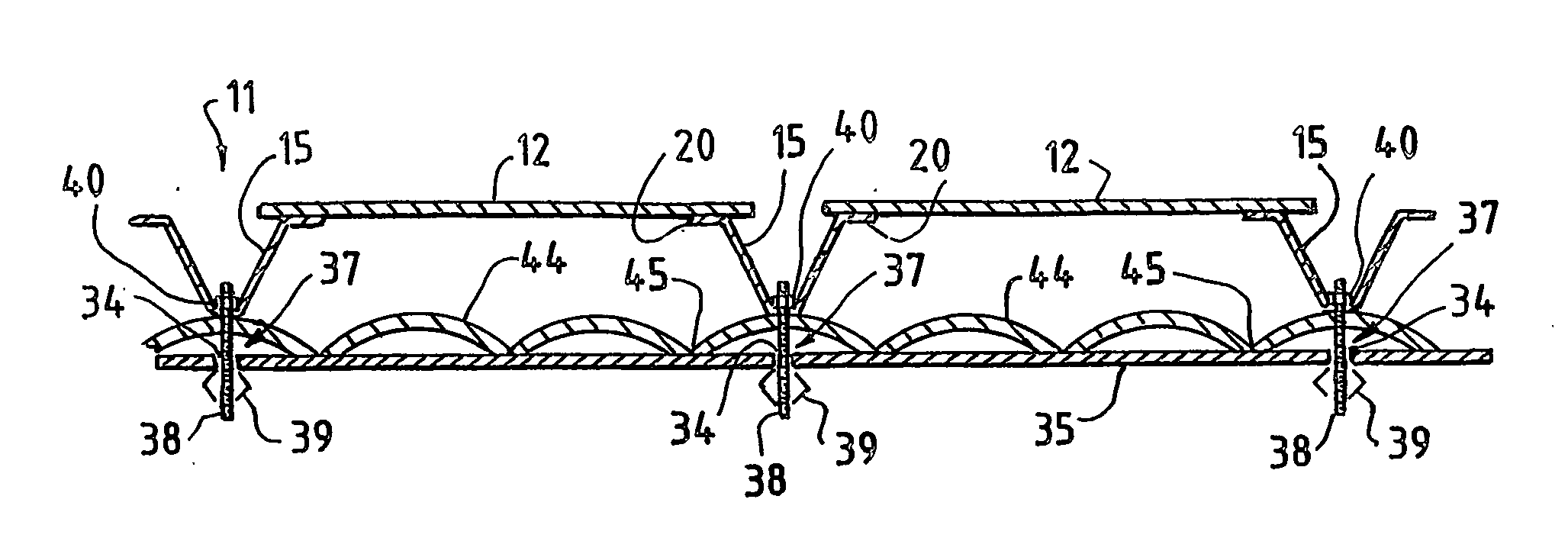
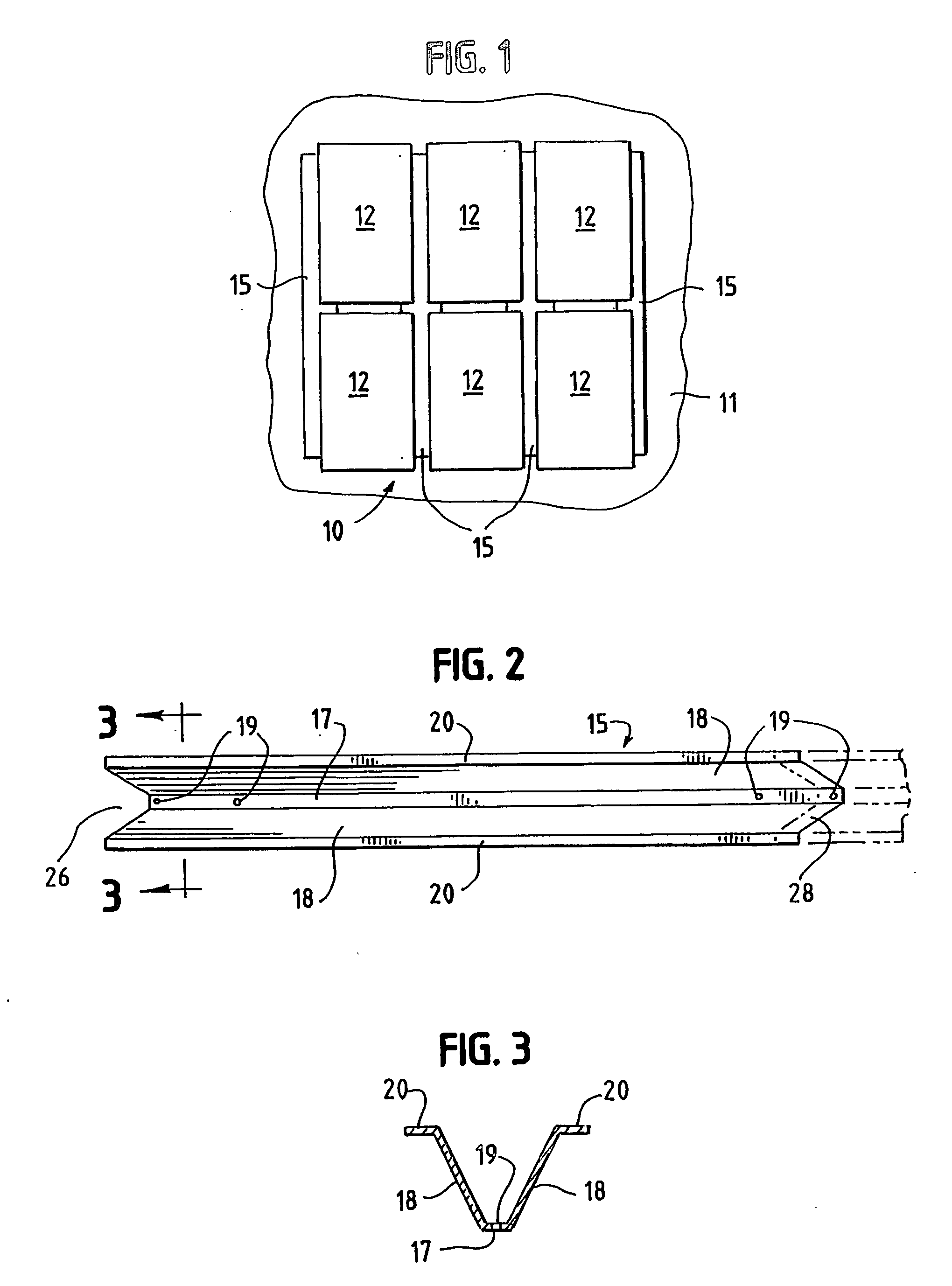
[0031] Referring now to the drawings, FIG. 1 illustrates a typical solar array 10 which has been mounted on a roof 11 in accordance with an embodiment of the present invention. Array 10 is comprised of a plurality (six shown) of solar laminates or modules 12, which have been positioned on and secured to mounting structures (i.e. pans 15 as will be more fully discussed below). As will be understood in the art, a laminate or module 12 (hereinafter “module”) is typically formed by positioning a plurality of photovoltaic cells (not shown) between a sheet of a transparent material (e.g. glass, plastic, etc.) and another sheet of, for example, opaque or transparent material, whereby the finished module is effectively a flat, plate-like structure as shown in the figures. The modules 12 are then positioned so that the photovoltaic cells will be exposed to the sun for converting its solar energy directly into electricity.

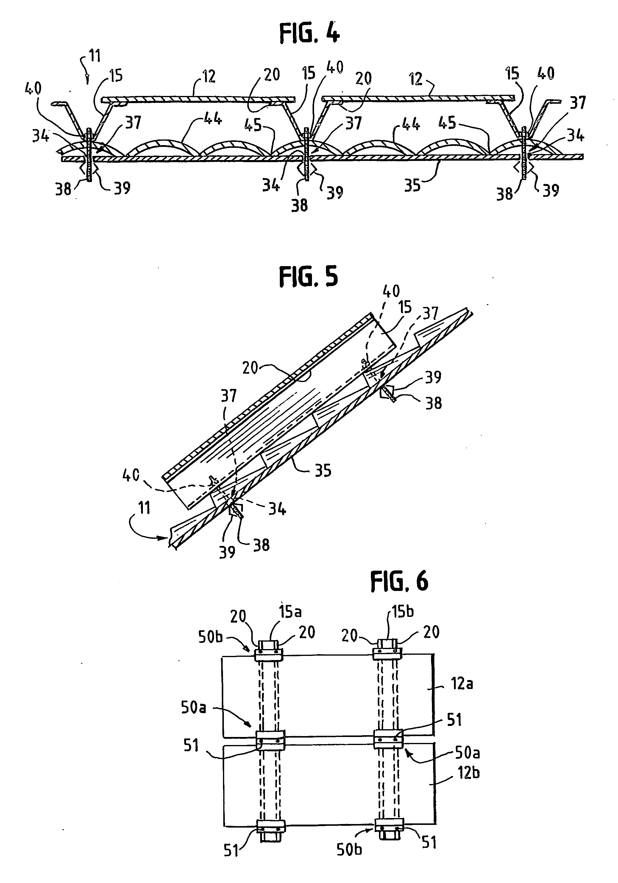
[0032] In accordance with the present invention, a unique mounting str...


PUM


Abstract

A method and apparatus for installing a solar array on the roof of a residence or the like which uses a pan in the installation of the solar modules that make up the array. The pan may also be used as part of the packaging of the solar modules. The pan is comprised of a length of material having a trough-like cross-section. For packaging, shipping inserts are fitted into the trough of each pan. Opposite edges of a solar module are fitted into respective slots in the inserts of two facing pans and a protector is fitted over each end thereof to form a package for shipping. Once on site, the packages are disassembled, the pans are mounted on the roof, and the modules are connected to the pans to form the array.

Description

[0001] This patent application claims the benefit of U.S. Provisional Patent Application 60 / 463,359 filed on Apr. 16, 2003.FIELD OF THE INVENTION [0002] The present invention relates to mounting solar energy modules on a roof or the like and in one of its aspects relates to the shipping solar modules to a site and then assembling the modules into an array which is mounted on the roof of a building such as a house or the like. BACKGROUND OF THE INVENTION [0003] In recent years, considerable advances have been made in using photovoltaic cells or the like to directly convert solar energy into useful electrical energy. Typically, a plurality of photovoltaic cells are encased between a transparent sheet (e.g. glass, plastic, etc.) and a transparent or opaque backsheet, to form flat, rectangular-shaped modules (sometimes also called “laminates”) of a manageable size (e.g. 2½′×5′). These modules are then shipped to a site where they are assembled into an array onto the roof of a building o...

Claims


Application Information

Patent Timeline
IPC IPC(8): E04D13/18E04H14/00H01L31/02H01L31/042H01L31/048
CPCF24J2/46F24J2/5205F24J2/5228F24J2/5245F24J2002/4669H02S20/23Y02B10/20Y02E10/47Y02E10/50H02S20/00Y02B10/12F24S25/33F24S25/40F24S25/61F24S80/00F24S2025/014F24S2025/6006Y02B10/10
Inventor WARFIELD, DONALDBGARVISON, PAUL L.ARNIN, DINESH S.
Owner BP CORP NORTH AMERICA INC
Why Eureka
Try Eureka