
Viscosity sensor system

a sensor system and viscosity technology, applied in the field of viscosity sensor system, can solve the problems of disadvantageous acquisition of separate sensors and temperature difference between the two sensor elements

Inactive Publication Date: 2006-12-14
ROBERT BOSCH GMBH
View PDF5 Cites 5 Cited by
  • Summary
  • Abstract
  • Description
  • Claims
  • Application Information

AI Technical Summary

Benefits of technology

The present invention provides a viscosity sensor system that combats the issues of spatial separation between sensor elements by combining a viscosity sensor with at least one additional sensor in a single sensor element. The additional sensor can acquire additional liquid properties and have electrical contact points for an electrical control device. The viscosity sensor device is formed as a disk-shaped quartz crystal that can be excited to shear oscillations by the electrical control unit, and the contact points of the viscosity sensor device are formed on the front and back side of the disk-shaped quartz crystal. The second sensor device can be electrically insulated from the viscosity sensor device. The first and second electrical supply lines are formed as contact springs. The viscosity sensor device can be situated in a protective container with base and cap and the first and second electrical supply lines are led out of the protective container through bushings, in particular glass bushings. The second sensor device can be a temperature sensor device or a capacitive sensor device.

Problems solved by technology

In particular when there are rapid changes in temperature (e.g. during the engine warmup phase) and temperature fluctuations (non-homogenous temperature distribution) in the liquid, the absence of this thermal contact results in a temperature difference between the two sensor elements.
For these quantities as well, acquisition by separate sensors proves to be disadvantageous.

Method used


Image

  • Viscosity sensor system
  • Viscosity sensor system
  • Viscosity sensor system

Examples


Embodiment Construction

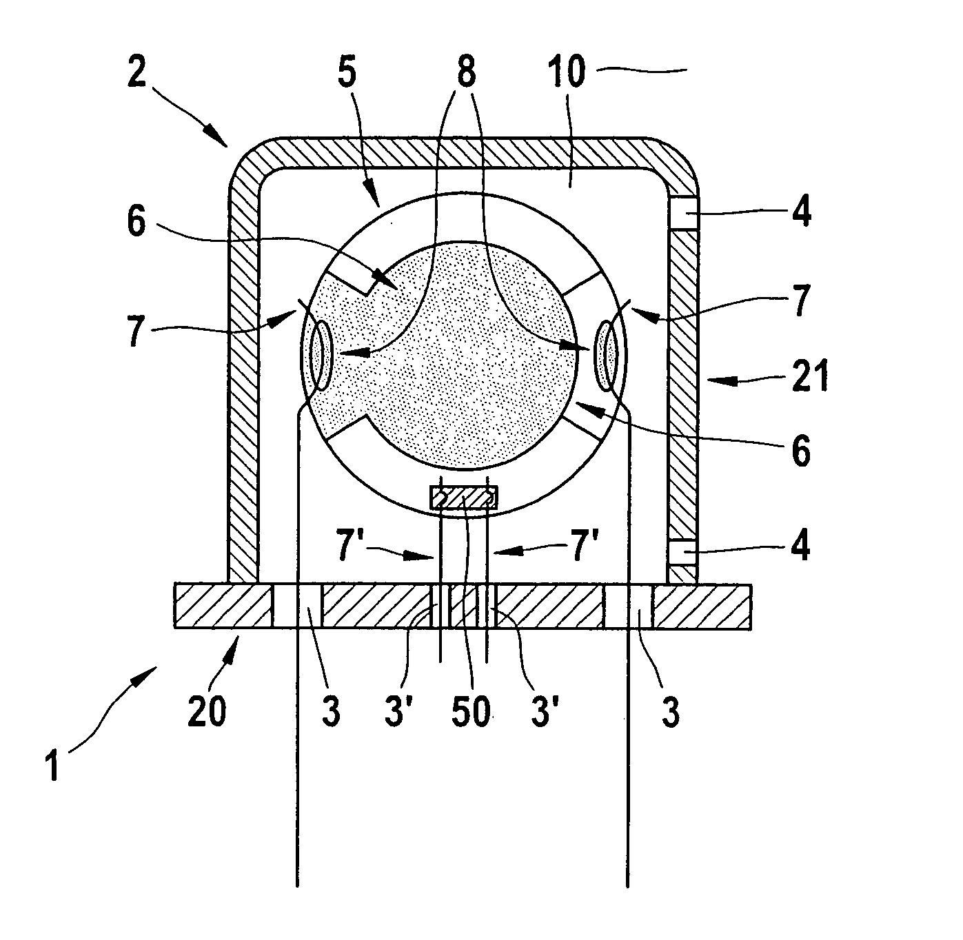
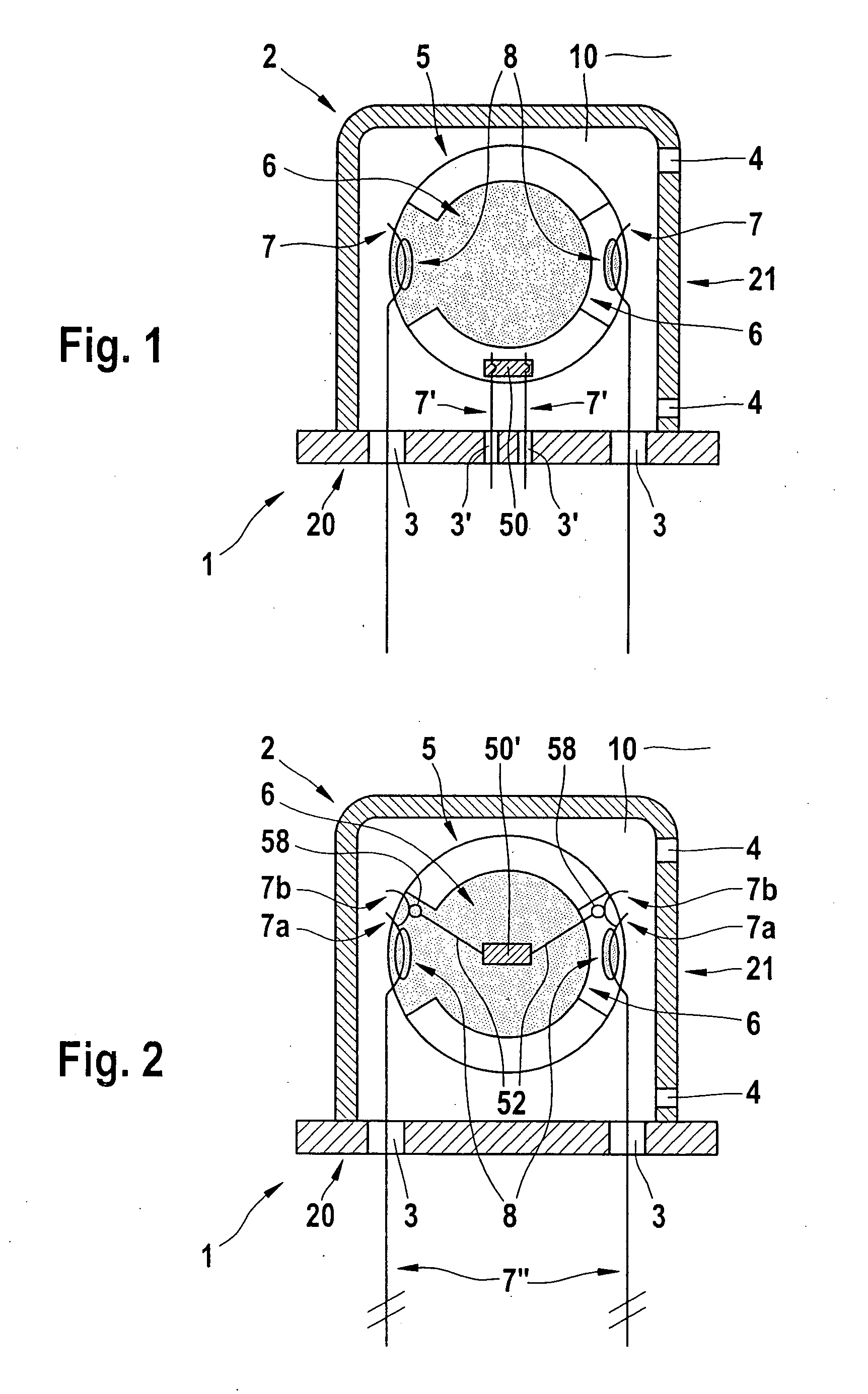
[0027]FIG. 1 shows a first specific embodiment of the viscosity sensor system according to the present invention, and its construction.

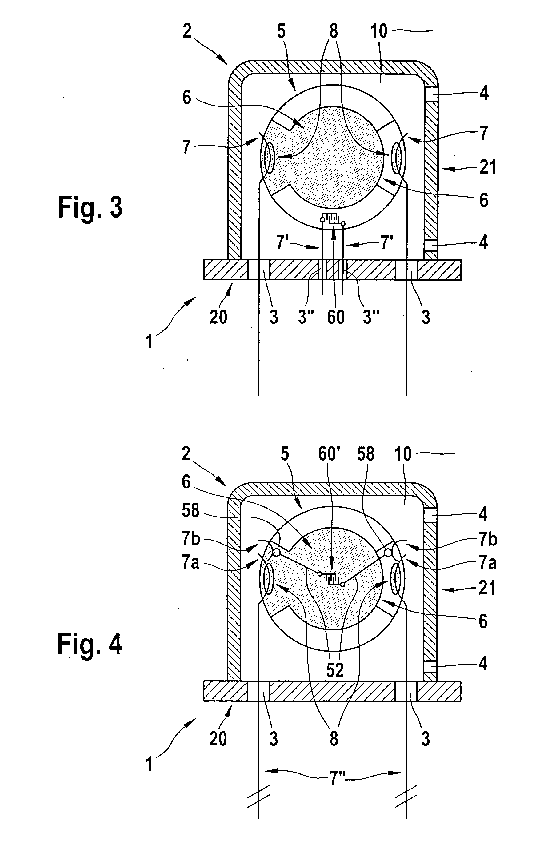
[0028] According to FIG. 1, a container 2 has two parts, being made up of a base 20 and a cap 21 attached detachably thereon, and is situated completely in a liquid 10 that is to be measured. Cap 21 has openings 4, situated laterally and / or at the top, for an exchange of liquid, the opening situated further toward the top being advantageously used as a liquid inlet and the opening situated further toward the bottom being advantageously used as a liquid outlet. Base 20 of container 2 has two pairs of glass bushings 3 and 3′.

[0029] As stated above, sensor system 1 is situated as a whole in a liquid 10 whose viscosity and / or other properties are to be measured. Through openings 4, the entire container 2 is thus also filled with liquid 10.

[0030] In the present, first exemplary embodiment, oil is used as the liquid 10, the materials used being suitably...


PUM

PropertyMeasurementUnit
sizeaaaaaaaaaa
viscosityaaaaaaaaaa
chemicalaaaaaaaaaa

Abstract

A viscosity sensor system for measuring the viscosity of a liquid and at least one additional property of the liquid using a piezoelectric viscosity sensor device that is situated completely in the liquid that is to be measured, and that has: electrical contact points for an electrical controlling of volume oscillations on its surface, these contact points being resistant in relation to the liquid; first electrical supply lines that are resistant in relation to the liquid and that are connected on the one hand with a control / evaluation electronics unit situated outside the liquid and on the other hand with the contact points on the surface of the viscosity sensor device; and a second sensor device for acquiring the at least one additional property of the liquid, this second device being provided on the surface of the viscosity sensor device and having electrical contact points on the surface of the viscosity sensor device for an electrical controlling, these electrical contact points being resistant in relation to the liquid; and second electrical supply lines that are resistant in relation to the liquid and that are connected on the one hand to the control / evaluation electronics unit situated outside the liquid and on the other hand to the contact points of the second sensor device.

Description

FIELD OF THE INVENTION [0001] The present invention relates to a viscosity sensor system. BACKGROUND INFORMATION [0002] In the monitoring of liquids, in particular liquid materials used in engine operation such as motor oil, a number of chemical and physical properties of the liquid can be used to monitor its “state”. An important criterion for monitoring the current state of the liquid is its viscosity η, which can be measured using a viscosity sensor. [0003] For the measurement of viscosity, piezoelectric thickness shear vibrators, made for example of quartz, have long been used. See for example S. J. Martin et al., Sens. Act. A 44 (1994), pp. 209-218. If such a thickness shear vibrator is immersed in a viscous liquid, the resonance frequency of its natural oscillation, and its damping, change in a manner dependent on the viscosity and the density of the viscous liquid. Because for typical liquids the density varies much less than does the viscosity, practically speaking such a co...

Claims


Application Information

Patent Timeline
Patent Type & Authority Applications(United States)
IPC IPC(8): G01N11/16G01N33/28
CPCG01N11/16G01N2011/0013G01N33/28
Inventor JAKOBY, BERNHARDBUSKIES, MATTHIASSCHERER, MONIKA
Owner ROBERT BOSCH GMBH
Learn More