Industrial two-layer fabric
a two-layer fabric and fabric technology, applied in the field of industrial two-layer fabric, can solve the problems of insufficient dehydration and severe requirements for papermaking wires, and achieve the effect of excellent surface properties and excellent breathability
- Summary
- Abstract
- Description
- Claims
- Application Information
AI Technical Summary
Benefits of technology
Problems solved by technology
Method used
Image

Examples
example 1
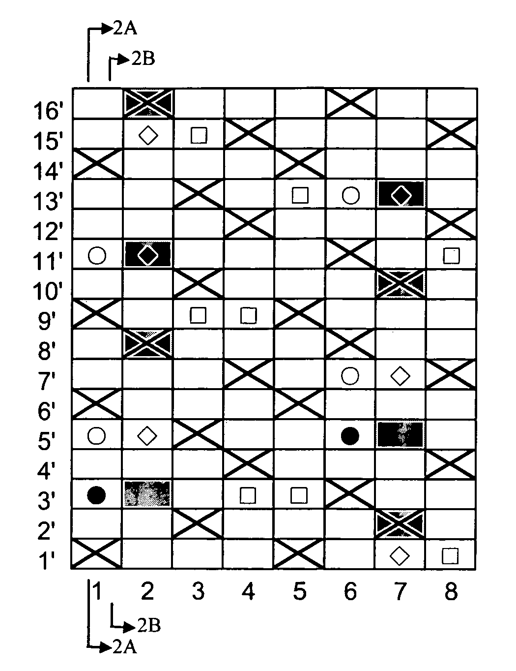
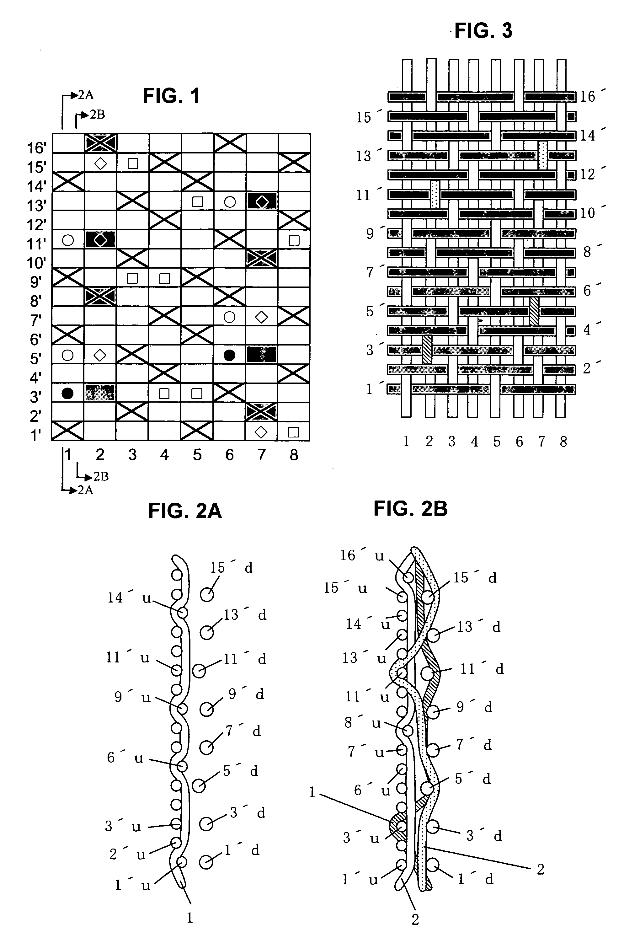
[0072]FIG. 1 is a design diagram showing a repeating unit of a fabric of Example 1 of the present invention. FIGS. 2A and 2B include cross-sectional views along the lines 2A-2A and 2B-2B of FIG. 1 which represent a first pair of first upper surface side warp 1 (FIG. 2A) and first lower warp binding yarn 1 (FIG. 2B), and a second pair of second upper surface side warp 2 and second lower warp binding yarn 2 (FIG. 2B) illustrated in the design diagram of FIG. 1 respectively. FIG. 3 is a plan view illustrating the upper side surface illustrated in the design diagram of FIG. 1. The fabric of this example is a two-layer 16-shaft fabric in which pairs of binding warps are arranged at a ratio of 4 / 8, while upper surface side wefts and lower surface side wefts are arranged at a ratio of 2:1.
[0073] In the design diagram of FIG. 1, indicated at numerals 1 and 6 are each a pair of first binding warps, 2 and 7 are each a pair of second binding warp, and 3, 4, 5 and 8 are each a pair of warps co...
example 2
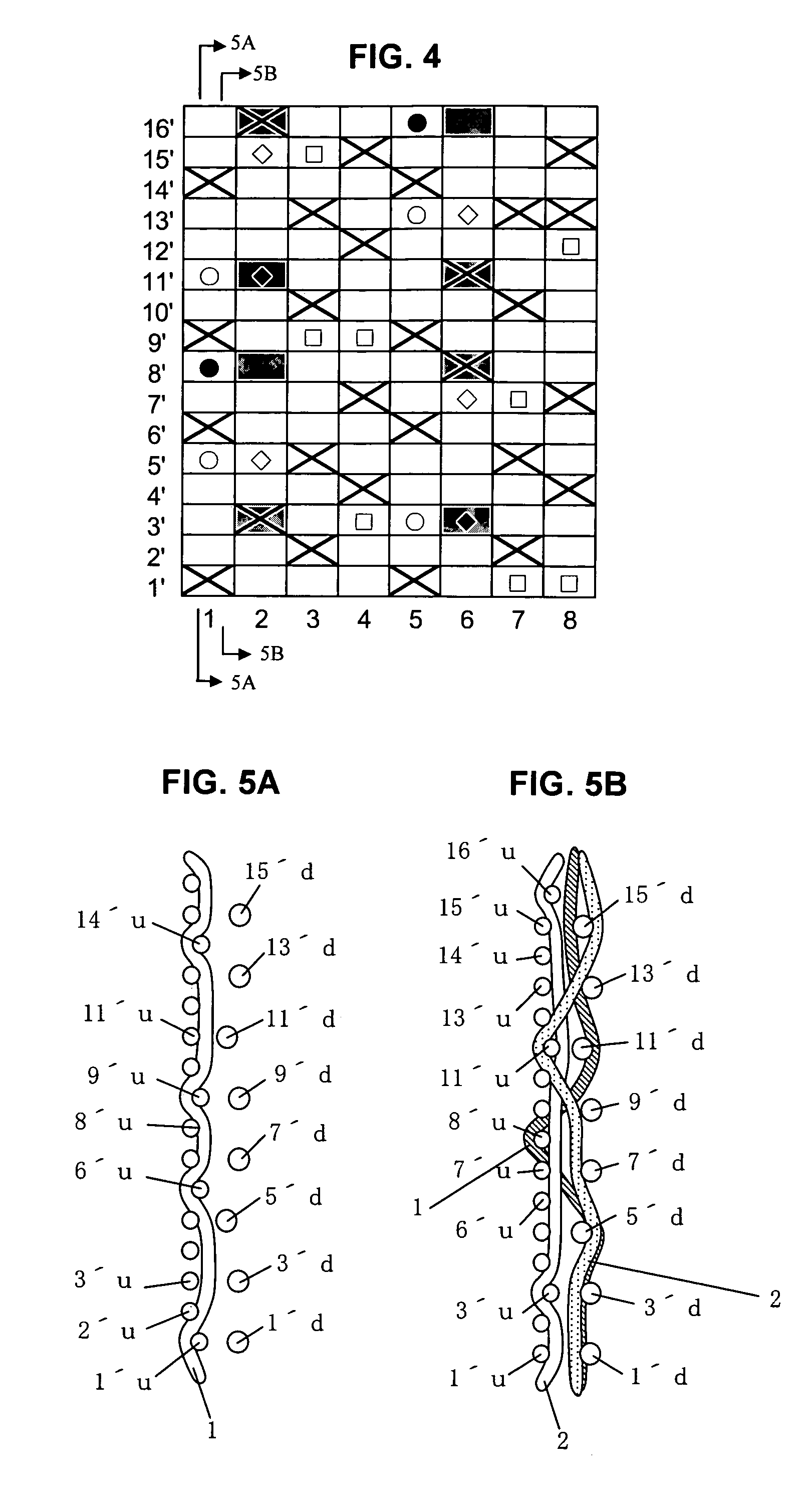
[0081]FIG. 4 is a design diagram showing a repeating unit of a fabric of Example 2 of the present invention. FIGS. 5A and 5B include cross-sectional views along lines 5A-5A and 5B-5B of FIG. 4 illustrating a first upper surface side warp 1 (FIG. 5A), and a first lower warp binding yarn 1 (FIG. 5B), a second upper surface side warp 2 and a second lower warp binding yarn 2 illustrated in the design diagram of FIG. 4.
[0082] In the design diagram of FIG. 4, indicated at numerals 1 and 5 are each a pair of first binding warps, 2 and 6 are each a pair of second binding warps, and 3, 4, 7 and 8 are each a pair of warps composed of an upper surface side warp and a lower surface side warp.
[0083] The upper side surface is, similar to Example 1, composed of warps having a 1 / 4-1 / 2 design and wefts having a 1 / 3 design. The first lower warp binding yarn 1, the second upper surface side warp 2 and the second lower warp binding yarn have respectively different designs, but the design formed by th...
example 3
[0088]FIG. 6 is a design diagram showing a repeating unit of a fabric of Example 3 of the present invention. FIGS. 7A and 7B include cross-sectional views along the lines 7A-7A and 7B-7B of FIG. 6 illustrating a first upper surface side warp 1 (FIG. 7A), and a first lower warp binding yarn 1 (FIG. 7B), a second upper surface side warp 2 and a second lower warp binding yarn 2 (FIG. 7B) illustrated in the design diagram of FIG. 6 respectively.
[0089] In the design diagram of FIG. 6, indicated at numerals 1 and 5 are each a pair of first binding warps, 2 and 6 are each a pair of second binding warps, and 3, 4, 7 and 8 are each a pair of warps composed of an upper surface side warp and a lower surface side warp.
[0090] The upper side surface is, similar to Example 1, composed of warps having a 1 / 4-1 / 2 design and wefts having a 1 / 3 design. The first lower warp binding yarn 1, the second upper surface side warp 2 and the second lower warp binding yarn 2 have respectively different designs...
PUM
 Abstract
Description
Claims
Application Information
 - R&D
- Intellectual Property
- Life Sciences
- Materials
- Tech Scout
- Unparalleled Data Quality
- Higher Quality Content
- 60% Fewer Hallucinations
Browse by: Latest US Patents, China's latest patents, Technical Efficacy Thesaurus, Application Domain, Technology Topic, Popular Technical Reports.
© 2025 PatSnap. All rights reserved.Legal|Privacy policy|Modern Slavery Act Transparency Statement|Sitemap|About US| Contact US: help@patsnap.com