Reflection type photoelectric switch

a photoelectric switch and reflection technology, applied in the direction of reradiation, counting objects on conveyors, instruments, etc., can solve the problems of inability to realize the miniaturization of the above-mentioned optical system, the size of the optical system is certain, and the miniaturization of the entire photoelectric switch is not realized. achieve the effect of high accuracy

Inactive Publication Date: 2006-12-14
KEYENCE
View PDF1 Cites 17 Cited by
  • Summary
  • Abstract
  • Description
  • Claims
  • Application Information

AI Technical Summary

Benefits of technology

[0006] Embodiments of the present invention provide a small size reflection type photoelectric switch which can detect an object with high accuracy.

Problems solved by technology

Therefore, in order to detect an object with high accuracy, there is such necessity that an optical system has a certain level of size, and miniaturization of the above-mentioned optical system has limitations.
In addition, even if it is tried to miniaturize an optical system by a method other than the above-mentioned one, miniaturization in an entire photoelectric switch is not realized, unless other members become reduced in size.
However, the flexible substrate is expensive as compared with the hard substrate, and therefore, when the flexible substrate is adopted, there is such a problem that it is not possible to configure a switch main body inexpensively.
Adjustment of a irradiated light amount of a light emitting element is carried out after the light receiving circuit substrate and the light emitting circuit substrate are incorporated in the first casing, but at this time, if the light receiving circuit substrate is disposed on the opening portion side rather than the light emitting circuit substrate, it is not possible to operate the variable resistor.

Method used


Image

  • Reflection type photoelectric switch
  • Reflection type photoelectric switch
  • Reflection type photoelectric switch

Examples


Embodiment Construction

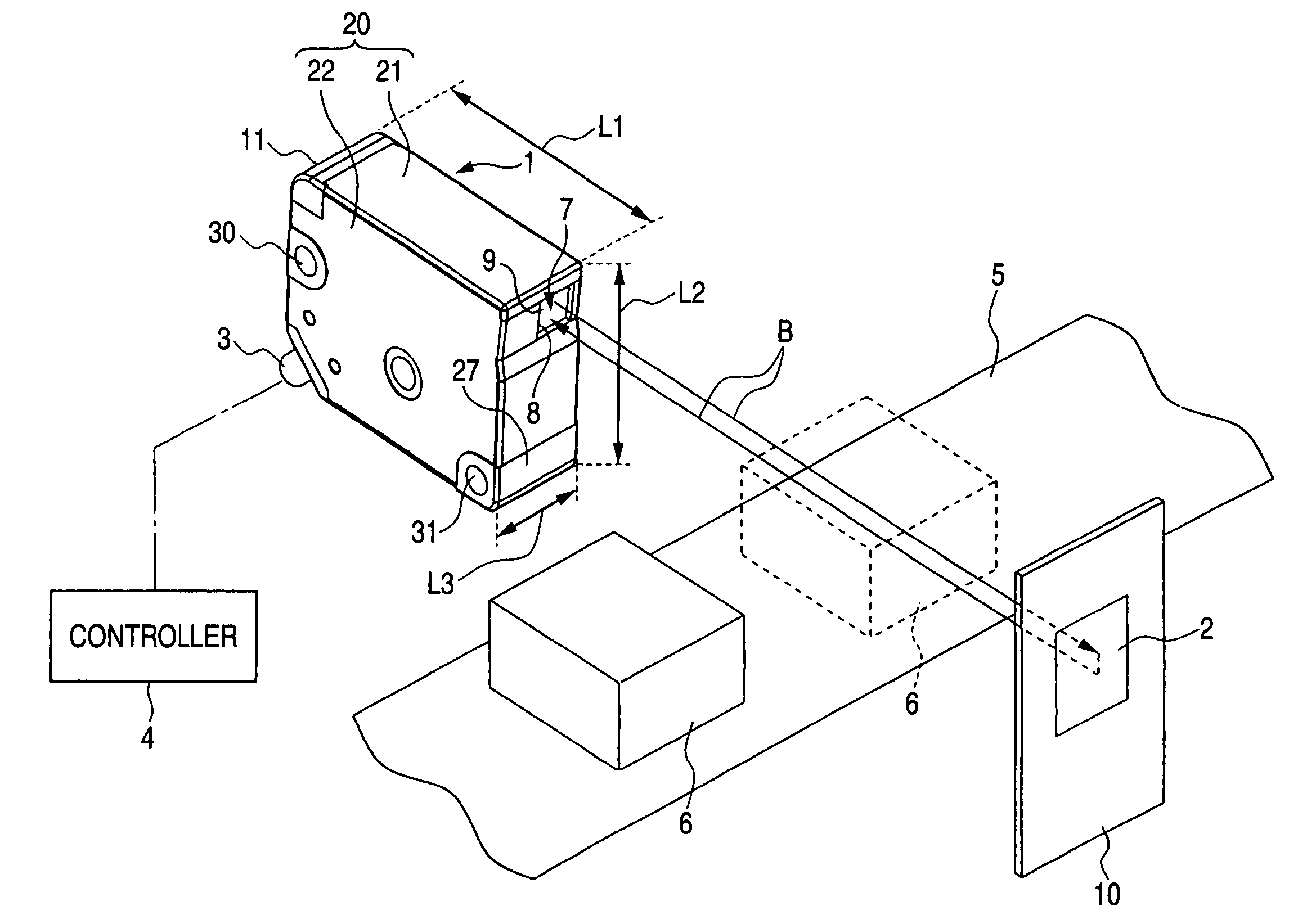
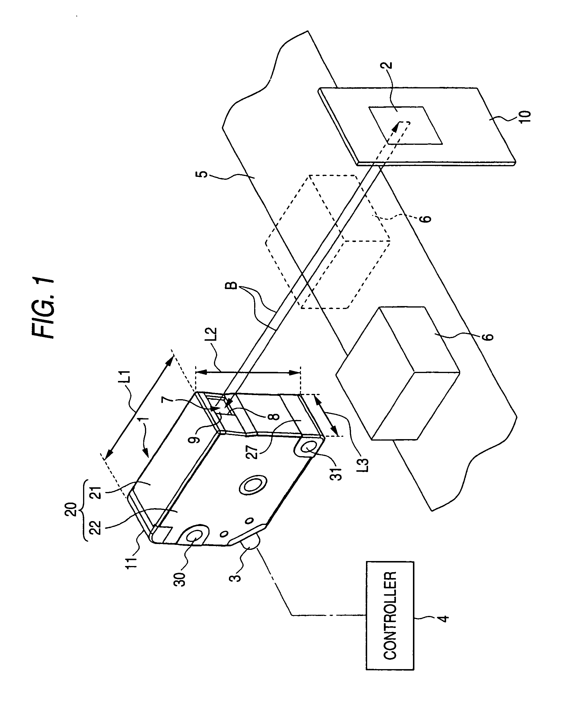
[0045]FIG. 1 is a schematic diagram which shows one configuration example of a regressive reflection type photoelectric switch according to an embodiment of the present invention. As shown in FIG. 1, this regressive reflection type photoelectric switch comprises a switch main body 1, a regressive reflection plate 2, and a controller 4. The switch main body 1 irradiates laser light B from a light emitting element and receives its reflected light by a light receiving element. The regressive reflection plate 2 reflects laser light B irradiated from the switch main body 1. The controller 4 is connected to the switch main body 1 through a cable 3 to control an operation of the switch main body 1.

[0046] This regressive reflection type photoelectric switch is disposed in a factory etc., and for example as shown in FIG. 1, used for detecting an object 6 which is conveyed on a belt conveyor 5. The switch main body 1 and the regressive reflection plate 2 are disposed so as to sandwich a conv...


PUM


Abstract

A circuit substrate is divided into a light emitting circuit substrate 60 and a light receiving circuit substrate 70, and they are disposed in a first casing 21 in a two-tier fashion, and the light emitting circuit substrate 60, which is disposed on an upper side, is overlapped with at least a part of an optical system 40. By this means, it is possible to obtain a wider range mounting surface in a small space, and therefore, it is possible to miniaturize a switch main body. In addition, it is possible to miniaturize the switch main body without miniaturizing the optical system 40 more than necessity, simply by changing a disposal configuration of components other than components of the optical system 40 in the switch main body, and therefore, it is possible to prevent lowering of detection accuracy which goes with miniaturization of the optical system 40, and it is possible to detect an object with high accuracy.

Description

TECHNICAL FIELD [0001] The present disclosure relates to a reflection type photoelectric switch. More particularly, the present disclosure relates to improvement of a disposal configuration of components which are disposed in a reflection type photoelectric switch. RELATED ART [0002] A regressive reflection type photoelectric switch has been known as a reflection type photoelectric switch which receives reflected light of light irradiated from a light emitting element, by a light receiving element, and detects an object on the basis of its amount of light received (e.g., Japanese Patent Unexamined Publication No. 2002-246636 which is referred as Patent Document 1, and Japanese-Patent Unexamined Publication No. 10-255611 which is referred as Patent Document 2). In the regressive reflection type photoelectric switch, laser right is irradiated toward a regressive reflection plate on which a three-dimensional reflection surface was formed by such a matter that a lot of protruding portio...

Claims


Application Information

Patent Timeline
Patent Type & Authority Applications(United States)
IPC IPC(8): G02B7/00
CPCG01S7/4812G01S7/4813G02B27/283G01V8/14G01S17/026G01S17/04
Inventor DEGUCHI, TOMOKIKOYAMA, KATSUNARI
Owner KEYENCE
Why Eureka
Try Eureka