Method and apparatus for dynamic allocation of pilot symbols

a pilot symbol and dynamic allocation technology, applied in the field of telecommunications, can solve the problems of relatively high cost of building or upgrading the telecommunication infrastructure to support growing consumer demand, virtually impossible to estimate the channel perfectly, and the rapid growth of customer demand for telecommunication services provided

Inactive Publication Date: 2006-12-14
LUCENT TECH INC
View PDF14 Cites 117 Cited by
  • Summary
  • Abstract
  • Description
  • Claims
  • Application Information

AI Technical Summary

Problems solved by technology

One of the paramount challenges facing modern telecommunication systems is the rapid growth of customer demand for telecommunications services provided by the Internet, the cellular telephone system, or other mechanisms.
Unfortunately, building or upgrading the telecommunication infrastructure to support growing consumer demand is relatively expensive.
One of the constant challenges in transmitting information is compensating for the effects of “the channel.” The channel includes the net effect of environmental factors, such as the weather, the earth's magnetic fields, terrain variations, structures, and / or vehicles on the electromagnetic signal as it travels through the air or another transmission medium from one device to another.
Unfortunately, it is virtually impossible to estimate the channel perfectly.
Thus, the receiver is typically not able to compensate completely for the channel and some distortion or errors are typically introduced.
Namely, there is a fixed bandwidth available for transmitting data and any bandwidth used to transmit pilot symbols is not available to transmit other (non-pilot) information.
If, however, channel conditions change during subsequent transmissions (e.g., later in a conversation), the number of pilot symbols or the allocation of pilot symbols may either become either insufficient or inefficient to maintain a desired signal-to-noise ratio (“SNR”).

Method used


Image

  • Method and apparatus for dynamic allocation of pilot symbols
  • Method and apparatus for dynamic allocation of pilot symbols
  • Method and apparatus for dynamic allocation of pilot symbols

Examples


Embodiment Construction

[0022] One or more specific embodiments of the present invention will be described below. In an effort to provide a concise description of these embodiments, not all features of an actual implementation are described in the specification. It should be appreciated that in the development of any such actual implementation, as in any engineering or design project, numerous implementation-specific decisions should be made to achieve the developers' specific goals, such as compliance with system-related and business-related constraints, which may vary from one implementation to another. Moreover, it should be appreciated that such a development effort might be complex and time consuming, but would nevertheless be a routine undertaking of design, fabrication, and manufacture for those of ordinary skill having the benefit of this disclosure.

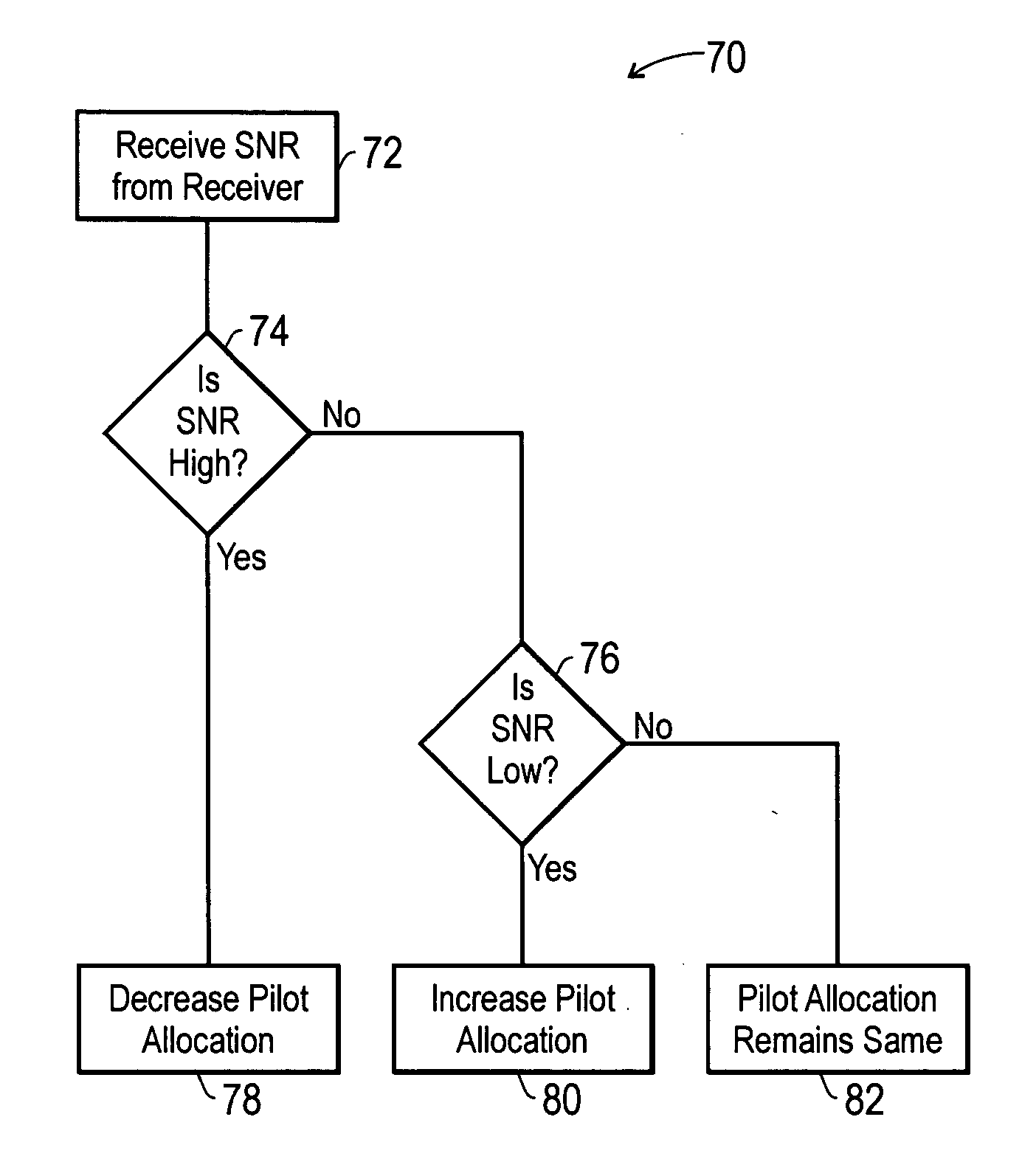
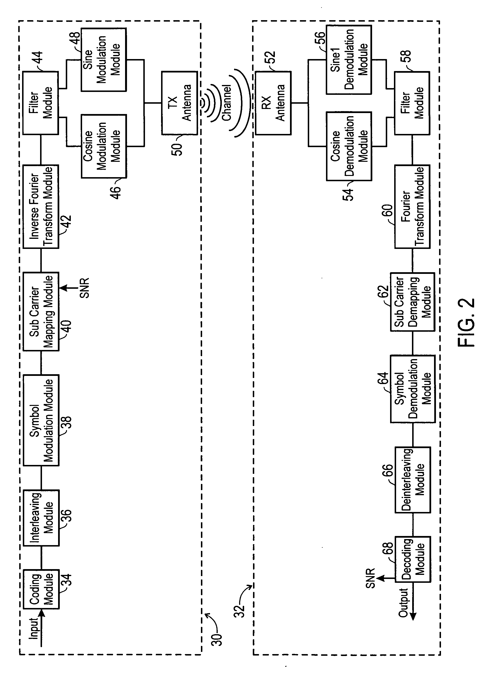
[0023] The embodiments described herein are directed towards a system or a method for dynamically allocating pilot symbols in an orthogonal frequency ...


PUM


Abstract

There is provided a method and apparatus for dynamic allocation of pilot symbols in an OFDM transmission. More specifically, there is provided a method comprising transmitting a first orthogonal frequency division multiplexed signal with a first pilot symbol allocation, receiving a metric indicative of the quality of a transmitted signal, changing the location of pilot symbols within the first pilot symbol allocation based on the metric to create a second pilot symbol allocation, and transmitting a second orthogonal frequency division multiplexed signal with the second pilot symbol allocation.

Description

BACKGROUND OF THE INVENTION [0001] 1. Field of the Invention [0002] The present invention relates generally to telecommunications and, more particularly to wireless communications. [0003] 2. Description of the Related Art [0004] This section is intended to introduce the reader to various aspects of art that may be related to various aspects of the present invention, which are described and claimed below. This discussion is believed to be helpful in providing the reader with background information to facilitate a better understanding of the various aspects of the present invention. Accordingly, it should be understood that these statements are to be read in this light, and not as admissions of prior art. [0005] One of the paramount challenges facing modern telecommunication systems is the rapid growth of customer demand for telecommunications services provided by the Internet, the cellular telephone system, or other mechanisms. In fact, consumers are demanding greater access to infor...

Claims


Application Information

Patent Timeline
Patent Type & Authority Applications(United States)
IPC IPC(8): H04J11/00
CPCH04L5/0007H04L5/0048H04L25/0232H04L25/0226H04L5/006
Inventor HUO, DAVID DI
Owner LUCENT TECH INC
Why Eureka
Try Eureka