Video display device and video display system
- Summary
- Abstract
- Description
- Claims
- Application Information
AI Technical Summary
Benefits of technology
Problems solved by technology
Method used
Image


Examples
first embodiment
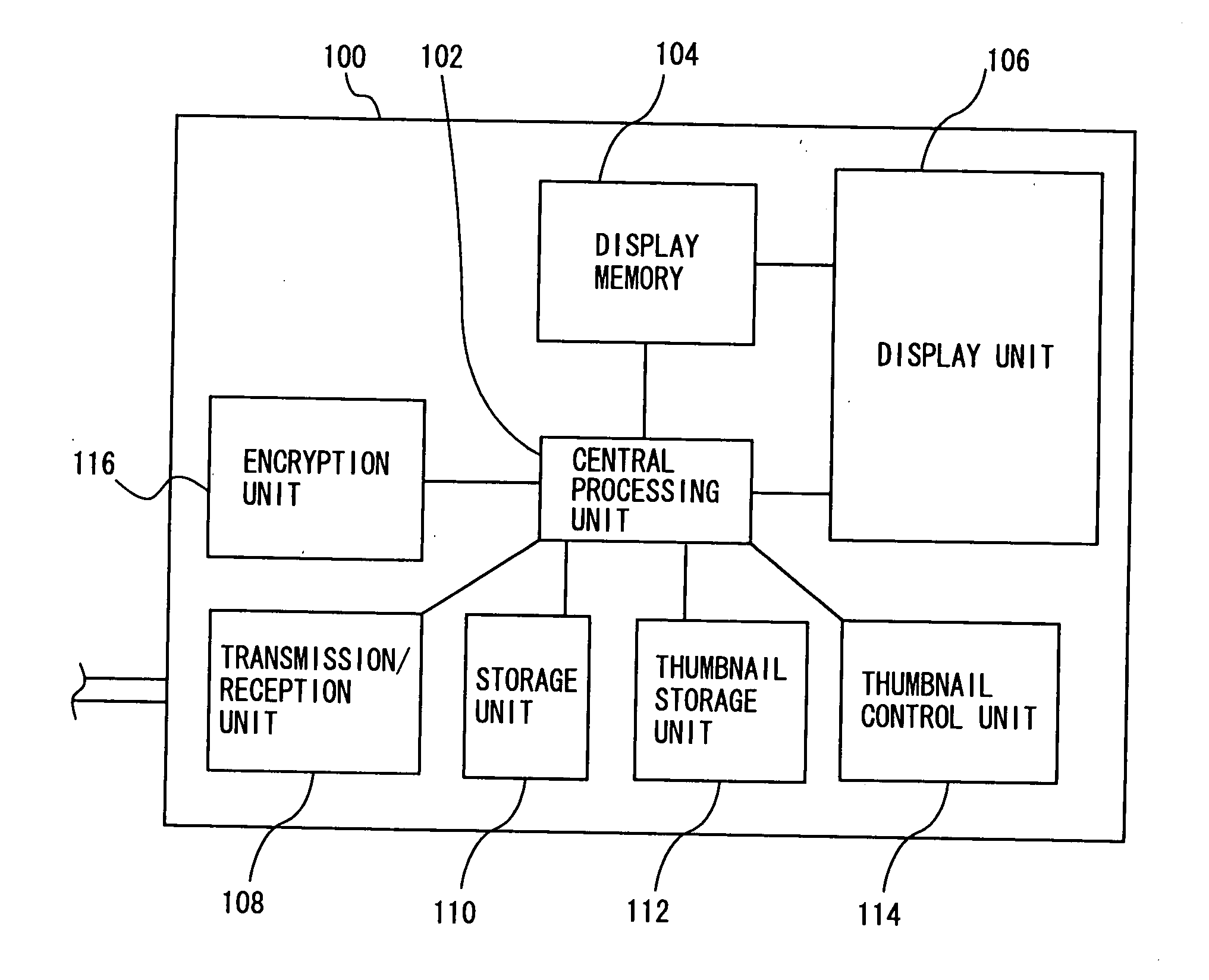
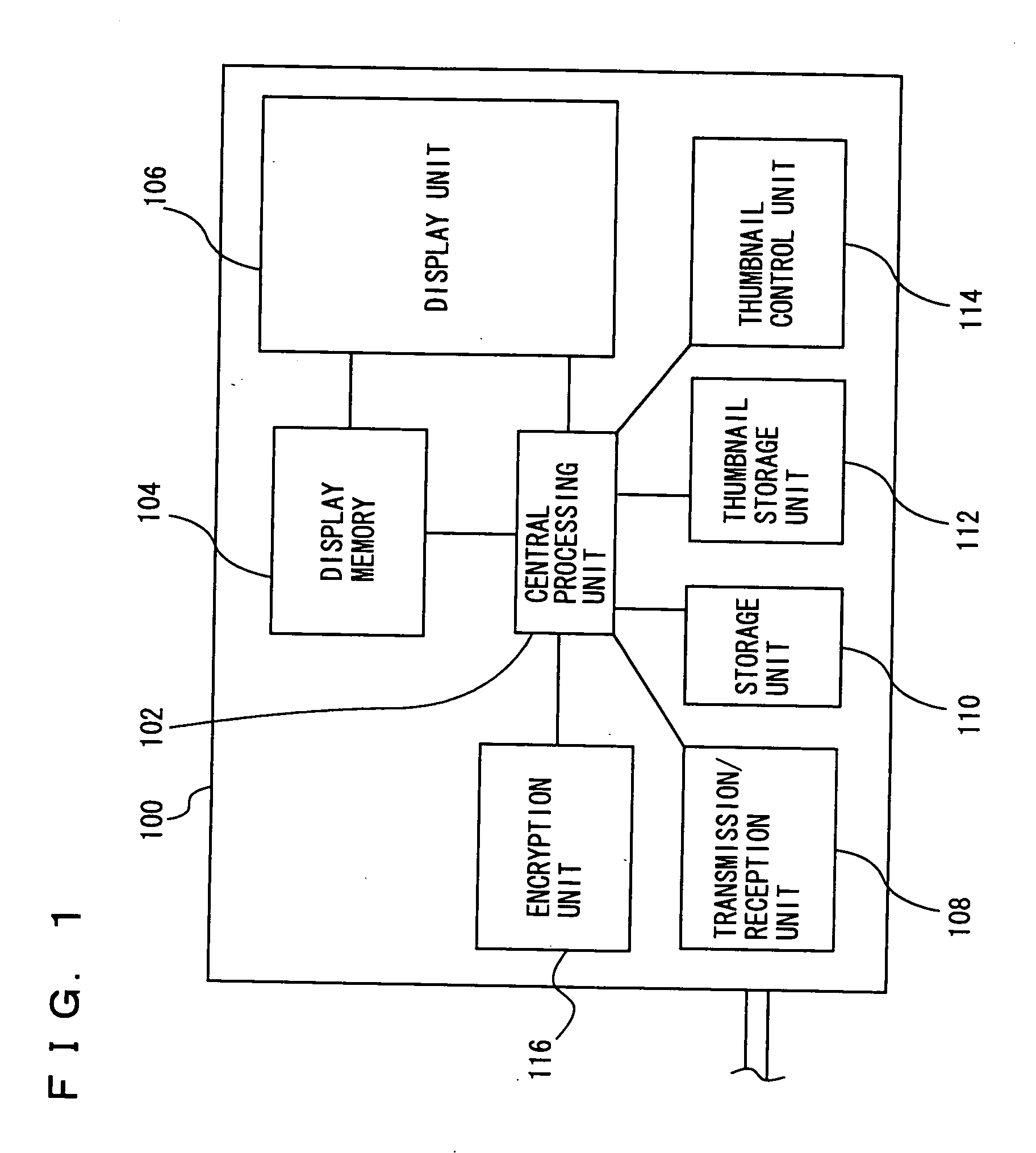
[0058] Referring to FIG. 1, the video display system in accordance with the present embodiment will be described. A video display device 100 included in the video display system includes a central processing unit 102, a display memory 104, a display unit 106, a transmission / reception unit 108, a storage unit 110, a thumbnail storage unit 112, a thumbnail control unit 114 and an encryption unit 116.
[0059] Central processing unit 102 is for overall control of video display device 100. Display memory 104 stores and successively sends to display unit 106 data for displaying contents and the like on display unit 106.
[0060] Display unit 106 displays data sent from display memory 104. Display unit 106 is formed, for example, by a liquid crystal display screen and its control unit. Transmission / reception unit 108 exchanges various pieces of information, contents and the like between video display device 100 and an external device.
[0061] Storage unit 110 is for storing contents and the li...
second embodiment
[0110] In the following, a second embodiment of the present invention will be described. The present embodiment differs from the first embodiment in that the thumbnail image is formed in video display device 100. Except for this point, the structure is the same as the first embodiment described above. The functions are also the same. Therefore, detailed description thereof will not be repeated here.
[0111] Referring to FIG. 9, video display device 100 in accordance with the present embodiment will be described. As shown in FIG. 9, video display device 100 includes a thumbnail forming unit 118. Thumbnail forming unit 118 does not obtain any thumbnail image from the outside. Thumbnail forming unit 118 forms, based on a content obtained through transmission / reception unit 108, a thumbnail image corresponding to the content.
[0112] Referring to FIG. 10, the control structure of the program executed by central processing unit 204 of video recording / reproducing device 200 of the video dis...
third embodiment
[0148] In the following, a third embodiment of the present invention will be described. The present embodiment differs from the first and second embodiments in that the thumbnail image is deleted when the power of video display device 100 is turned off.
[0149] Except for this point, the structure is the same as the first and second embodiments described above. The functions are also the same. Therefore, detailed description thereof will not be repeated here.
[0150] Referring to FIG. 13, video display device 100 of the video display system in accordance with the present embodiment will be described. As shown in FIG. 13, on display unit 106 of video display device 100 in accordance with the present embodiment, a power-off button 120 for instructing power-off is displayed.
[0151] The power-off button 120 is similar to one displayed on a image screen of a commonly used personal computer. By clicking the power-off button using a remote controller or a mouse, the user can instruct power-o...
PUM
 Abstract
Description
Claims
Application Information
 - R&D
- Intellectual Property
- Life Sciences
- Materials
- Tech Scout
- Unparalleled Data Quality
- Higher Quality Content
- 60% Fewer Hallucinations
Browse by: Latest US Patents, China's latest patents, Technical Efficacy Thesaurus, Application Domain, Technology Topic, Popular Technical Reports.
© 2025 PatSnap. All rights reserved.Legal|Privacy policy|Modern Slavery Act Transparency Statement|Sitemap|About US| Contact US: help@patsnap.com