Tool holding structure

a tool and tool technology, applied in the field of tool holding structure, can solve the problems of easy error in tool mounting, tool shake, unrealistic high-speed spindle mounting mechanism, etc., and achieve the effect of reducing the tolerance between the outer diameter and the tool, improving reliability, and facilitating movemen

Inactive Publication Date: 2006-12-14
FANUC LTD
View PDF11 Cites 3 Cited by
  • Summary
  • Abstract
  • Description
  • Claims
  • Application Information

AI Technical Summary

Benefits of technology

[0016] The tool holding structure according to the present invention is a simple one, thereby leading to improved reliability. In addition, provided that the shank supporting parts are made precisely and the tolerance between the outer diameter and the tool is minimized, the present invention can easily achieve precise tool holding even with the pin gauge class of tool shanks employed in tools used in ultra-precise machining applications.

Problems solved by technology

However, when a collet-type chuck is used, it is easy for tool mounting error to arise depending on the accuracy of the dimensions of the tapered portions of the collet and the spindle.
In addition, mounting a mechanism like a hydraulic chuck on a small, high-speed spindle is unrealistic due to the design difficulties involved.
As a result, the tool shakes due to the angle of insertion and the like and there is a risk that an error arises in the orientation of the mounting.
In a machine tool, any imbalance in or inaccuracy in mounting of the tool affects machining, and therefore precise holding of the tool and repetitive accuracy of tool replacement are required.

Method used


Image

  • Tool holding structure
  • Tool holding structure
  • Tool holding structure

Examples


Embodiment Construction

[0022] A detailed description will now be given of embodiments of the present invention, with reference to the accompanying drawings.

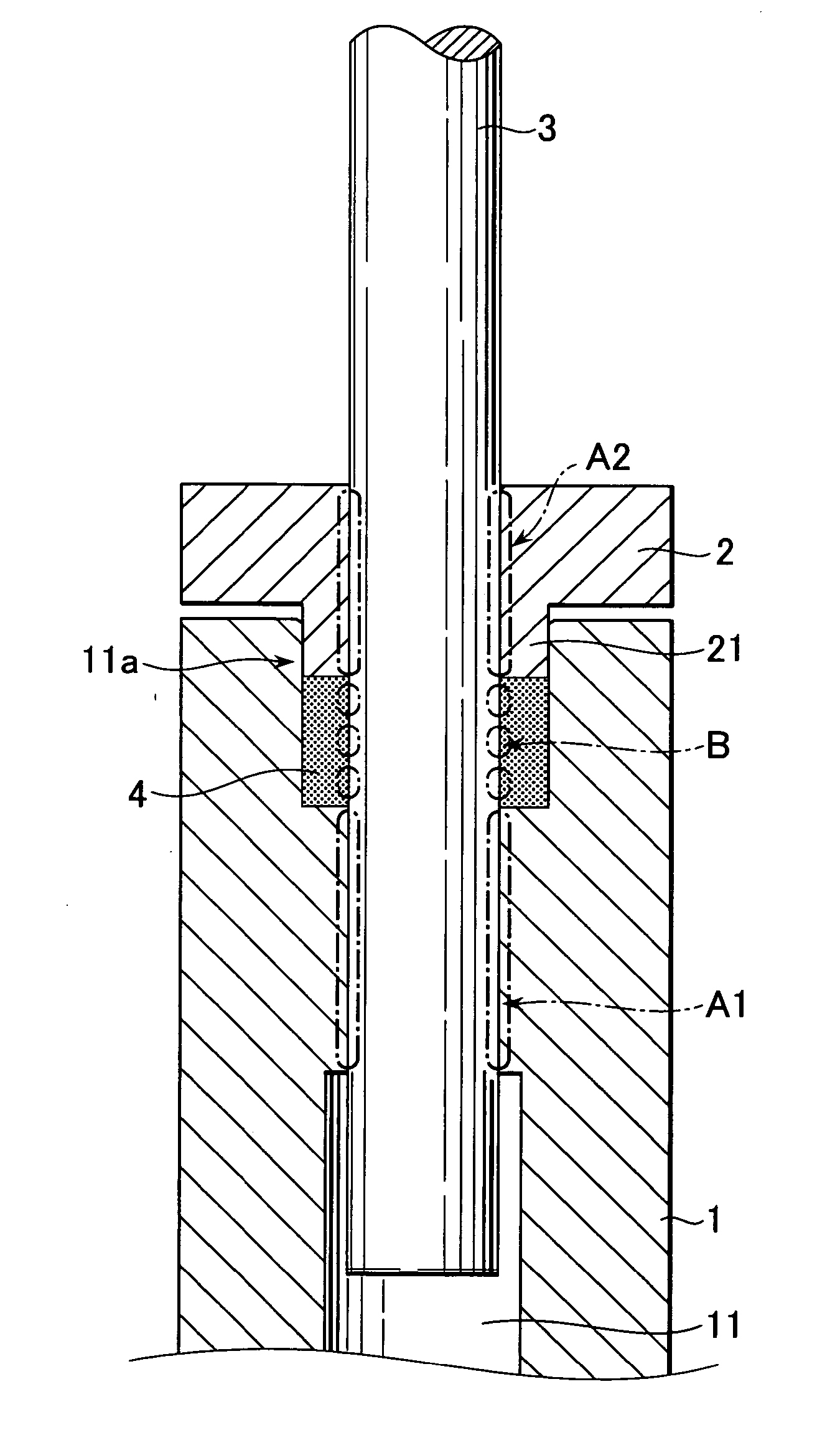
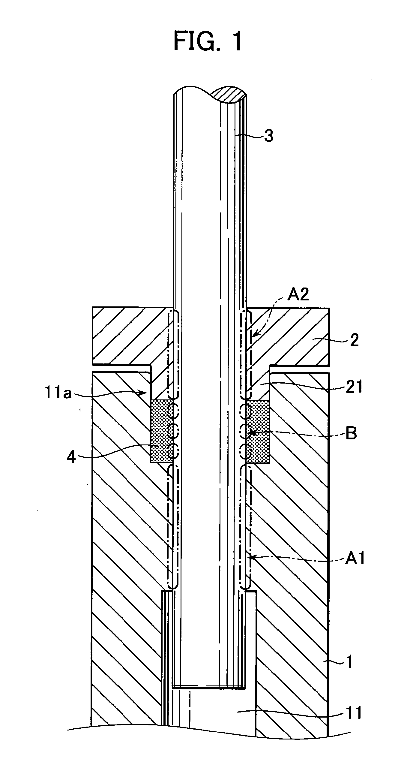
[0023]FIG. 1 is a diagram showing a sectional view along the axis of a spindle, indicating the main features of a tool holding structure according to one embodiment of the present invention. In FIG. 1, reference numeral 1 indicates the spindle of a machine tool, which has a tool shank insertion hole 11 extending axially along the spindle 1. Reference numeral 2 indicates a sleeve mounted coaxially on the spindle 1, having an insertion part 21 inserted into a large diameter part 11a formed on the entry side of the tool shank insertion hole 11.

[0024] The inner peripheral surface of the large diameter part 11a and the outer peripheral surface of the insertion part 21 are shaped and sized to match each other precisely. The sleeve 2 further has a through hole through which a tool shank 3 is passed. This through hole is shaped to be precisely concentric wit...


PUM

PropertyMeasurementUnit
elasticaaaaaaaaaa
annular shapeaaaaaaaaaa
compressive forceaaaaaaaaaa

Abstract

The invention provides a simplified holding structure for a tool for a machine tool that makes accurate tool holding possible. The tool shank is inserted through a through hole of a sleeve and into a tool shank insertion hole. The sleeve insertion part is inserted into a large-diameter part and fixed coaxially to the spindle with bolts or the like, so as to axially compress at least one annular elastic member provided on the large-diameter part. A first shank-supporting portion is provide inside the tool shank insertion hole and a second shank-supporting portion is provided on the sleeve through hole. A front end part of the insertion part is semicircular or trapezoidal in axial cross-section. The tool shank insertion hole, the sleeve through hole and the annular elastic member have cross-sections in directions perpendicular to the axis of the tool shank shaped that match the tool shank.

Description

BACKGROUND OF THE INVENTION [0001] 1. Field of the Invention [0002] The present invention relates to tool holding of a machine tool, and more particularly to a tool holding structure for holding and clamping a tool shank to a spindle of the machine tool. [0003] 2. Description of the Related Art [0004] In the conventional art, collet chucks and hydraulic chucks are widely used for tool holding of machine tools. However, when a collet-type chuck is used, it is easy for tool mounting error to arise depending on the accuracy of the dimensions of the tapered portions of the collet and the spindle. In addition, mounting a mechanism like a hydraulic chuck on a small, high-speed spindle is unrealistic due to the design difficulties involved. Moreover, a variety of technologies relating to tool holding for machine tools have been proposed, and are also disclosed in patent publications. [0005] JP 11-77413A is a typical example thereof, and discloses a bellows-shaped holder for holding a tool....

Claims


Application Information

Patent Timeline
Patent Type & Authority Applications(United States)
IPC IPC(8): B23C5/26
CPCY10T409/309464B23B31/1175
Inventor KAWAI, TOMOHIKOEBIHARA, KENZOOOKI, TAKESHI
Owner FANUC LTD
Why Eureka
Try Eureka