Battery electrolyte level control system

a level control system and battery electrolyte technology, applied in secondary cell servicing/maintenance, cell components, instruments, etc., can solve the problems of manual battery maintenance procedures that cannot be attended to by skilled on-duty personnel, electrolyte overflow during subsequent charging, and a significant danger to personnel, vehicles and surrounding flooring, so as to improve safety and maintain battery life , the effect of minimizing the risk of spillag

Inactive Publication Date: 2006-12-14
AEROVIRONMENT INC
View PDF18 Cites 21 Cited by
  • Summary
  • Abstract
  • Description
  • Claims
  • Application Information

AI Technical Summary

Benefits of technology

[0007] In various embodiments, the present invention solves some or all of the needs mentioned above, providing an electrolyte raising system that can maintain battery life a

Problems solved by technology

In these remote locations, skilled on-duty personnel may not be available to attend to manual battery maintenance procedures, such as checking and refilling electrolyte levels at the proper times.
Nevertheless, because electrolyte is displaced when the state of charge of the battery is increased, batteries that have water added during a low state of charge may have an electrolyte overflow while subsequently being charged.
The overflowing electrolyte may be very acidic (e.g., it may contain a strong solution of hydrochloric acid), and can present a significant danger to personnel, vehicles and the surrounding flooring.
For such a fleet of vehicles,

Method used


Image

  • Battery electrolyte level control system
  • Battery electrolyte level control system
  • Battery electrolyte level control system

Examples


first embodiment

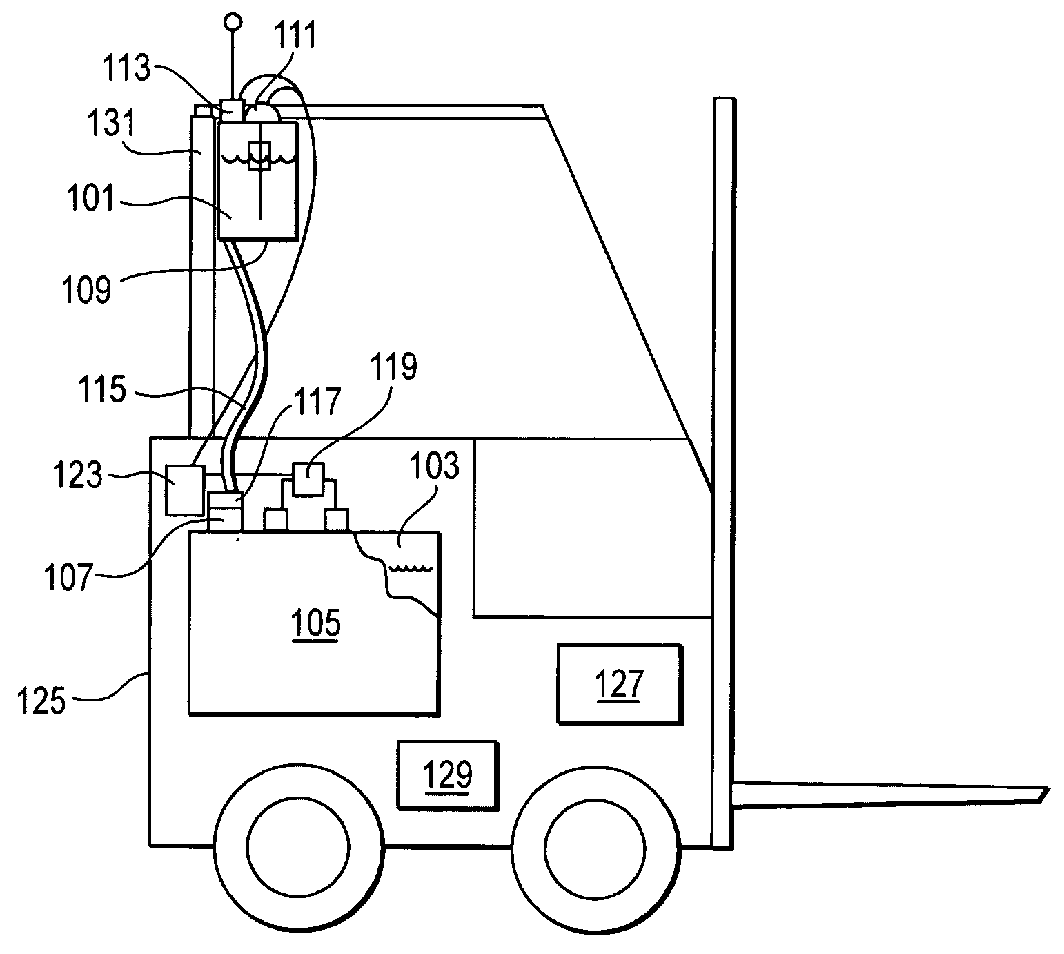
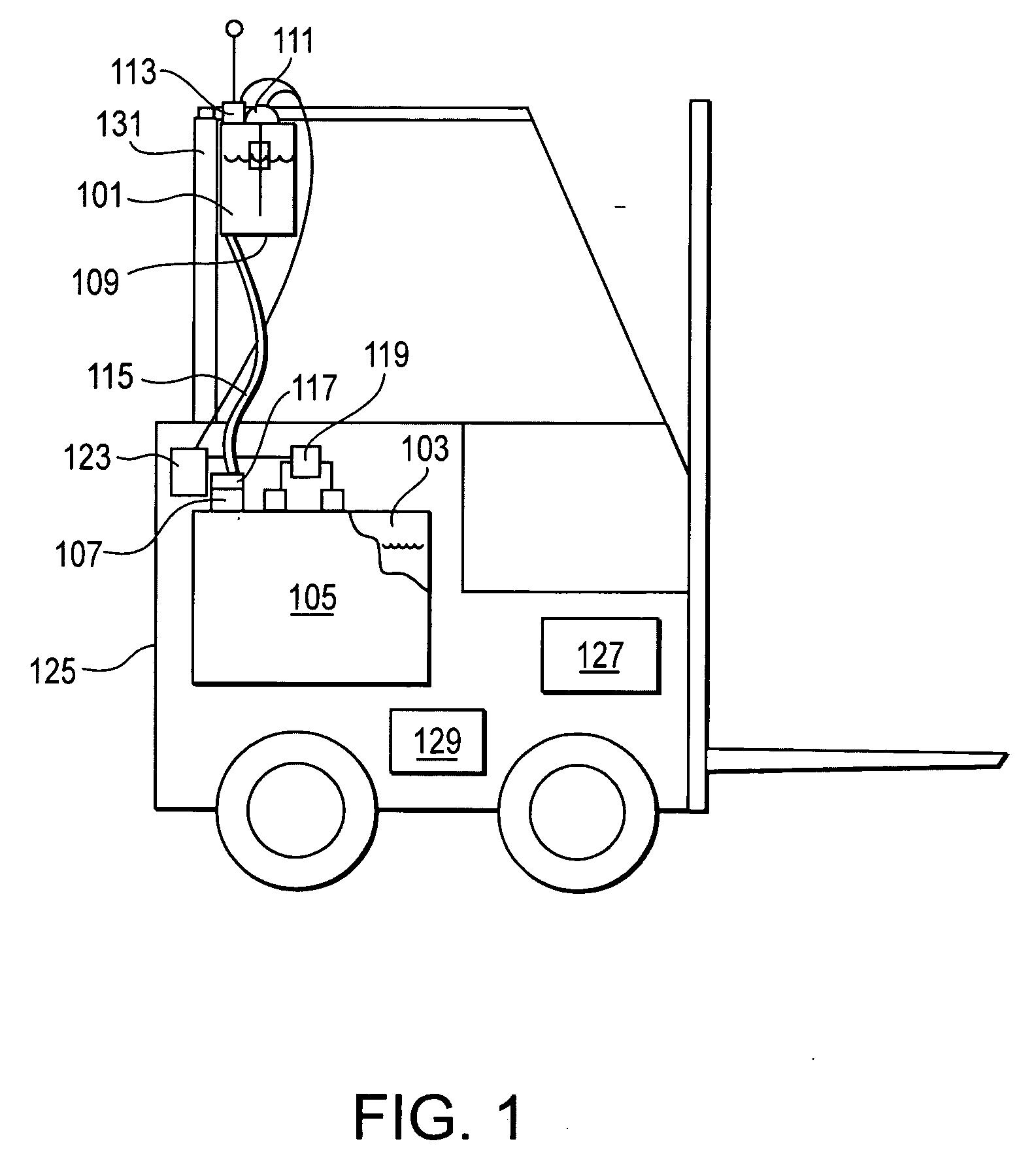
[0018] With reference to FIG. 1, a system for adding a quantity of fluid, e.g., water 101, to raise the electrolyte level in a battery chamber 103 within a battery 105 having a hydro-mechanical cutoff valve 107, includes a reservoir 109, a reservoir-level sensor 111, a transmitter 113, a distribution system 115, a solenoid valve 117, a battery-charge sensor 119 and a battery-electrolyte control system 123. This embodiment is configured for use in a vehicle 125, such as a forklift having a lift controller 127 and a drive controller 129. The vehicle may be operated in isolation, or may be part of a fleet of two or more of such vehicles, each of which is preferably provided with its own system for adding water to its battery under the present invention.

[0019] The reservoir 109 forms a translucent-walled chamber that is configured to contain water, and may preferably have a capacity of somewhere between one and five gallons. Because the reservoir chamber has translucent walls, the water...

second embodiment

[0036] With reference to FIG. 3, a system for adding a quantity of fluid, e.g., water 201, to raise the electrolyte level in a battery chamber 203 within a battery 205 having a hydro-mechanical cutoff valve 207, includes a reservoir 209, a reservoir-level sensor 211, a transmitter 213, a distribution system 215, a solenoid valve 217, a battery-charge sensor 219, a battery-electrolyte-level sensor 221 and a battery-electrolyte control system 223. This embodiment is configured for use in a vehicle 225, such as a forklift having a lift controller 227 and a drive controller 229. The vehicle is part of a fleet of two or more of such vehicles, each of which is preferably provided with its own system for adding water to its battery under the present invention.

[0037] As previously described, the reservoir 209 forms a translucent-walled chamber that is configured to contain water, and preferably has a capacity of somewhere between one and five gallons. As before, the reservoir 209 is prefera...


PUM


Abstract

An electrolyte level control system for adding a quantity of water to raise the electrolyte level in a forklift battery having a hydro-mechanical cutoff valve. The system includes a reservoir, a reservoir-level sensor, a transmitter, a distribution system, a battery-charge sensor, a solenoid valve, a battery electrolyte level sensor, and a battery-electrolyte control system that controls the position of the solenoid valve in light of the detection of a battery state of charge from the battery charge sensor, and the detection of the battery electrolyte level from the battery electrolyte level sensor. The system provides for watering the battery when the state of charge is full and the electrolyte level is not full.

Description

[0001] This application claims the benefit of U.S. provisional Application No. 60 / 685,735, filed May 28, 2005, which is incorporated herein by reference for all purposes.[0002] The present invention relates generally to a battery electrolyte refill system, and, more particularly, to an apparatus and related methods for adding water to the electrolyte of a battery at times conducive to maintaining battery life while avoiding electrolyte overflow during periods of battery recharging. BACKGROUND OF THE INVENTION [0003] Battery-operated vehicles, such as forklifts, trucks, golf carts, and the like, require periodic recharging. To maintain the battery life of the batteries in such vehicles, the battery electrolyte levels need to be replenished regularly. In many cases, busy fleets of these vehicles are maintained and used by a variety of personnel who may lack the time, training, and / or motivation to properly service the batteries. Moreover, leading-edge battery charging systems now oper...

Claims


Application Information

Patent Timeline
IPC IPC(8): H01M2/36H01M10/44H01M50/673
CPCB66F9/24G01F23/0007G01F23/02H01M10/484H01M2/362H01M10/4214G05D9/12Y02E60/10H01M50/673
Inventor HAYASHIGAWA, LARRY
Owner AEROVIRONMENT INC
Why Eureka
Try Eureka