
Two-step battery charger

a charger and battery technology, applied in the field of chargers, can solve the problems of reducing the reducing the service life of the battery, so as to reduce the voltage, shorten the charging time, and increase the current

Inactive Publication Date: 2009-06-23
ASIAN POWER DEVICES
View PDF2 Cites 7 Cited by
  • Summary
  • Abstract
  • Description
  • Claims
  • Application Information

AI Technical Summary

Benefits of technology

"The invention provides a two-step charger that adjusts the charging current based on the battery's charging status to balance charging time and battery lifetime. The charger includes an AC / DC power supply, transformer, compensator, controller, comparator, and isolating controller. The charger uses the comparator to detect if a battery is connected to the transformer and sends a compensating current to increase the current entering the transformer and thus the current output by the secondary side of the transformer. Once the battery is fully charged, the voltage is lowered to reduce the current entering the battery and helps reducing the temperature on the battery. This helps maintaining the battery's lifetime while sacrificing charging time."

Problems solved by technology

For example, non-rechargeable batteries contain materials harmful to the environment.
Although this method can finish charging in a shorter time, people normally do not immediately remove the batteries from the charger once it is done.
Therefore, the larger current usually produces a high temperature on the batteries.
If the batteries are exposed to the high temperature for a long time, their lifetime may be greatly shortened.
As a result, the charging time is longer.
It may take several hours to charge a battery in this scheme.
Therefore, it is inconvenient.
From the above description, it is seen that current chargers are unable to charge batteries at a quicker speed without sacrificing their lifetime.

Method used


Image

  • Two-step battery charger
  • Two-step battery charger
  • Two-step battery charger

Examples


Embodiment Construction

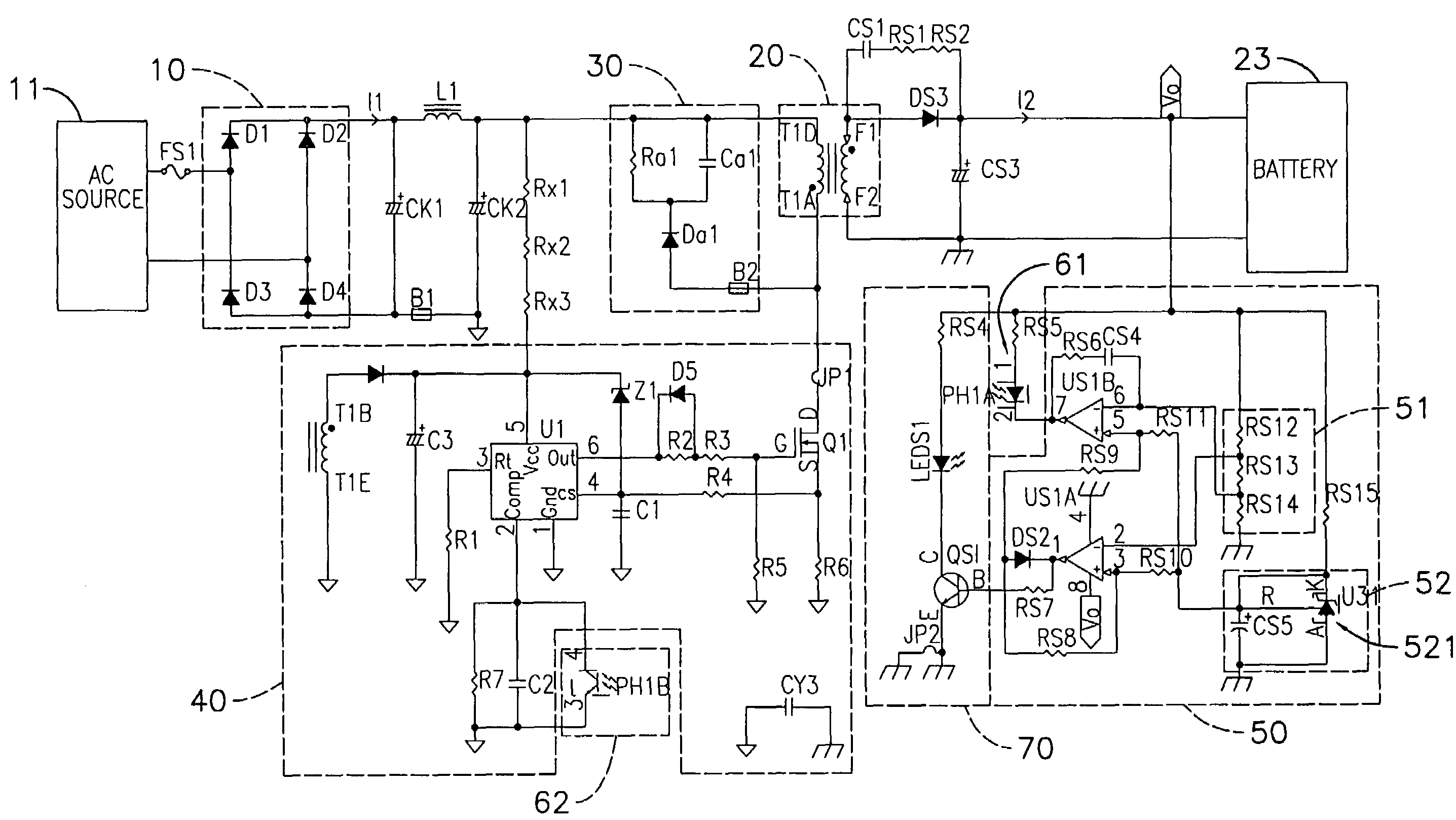
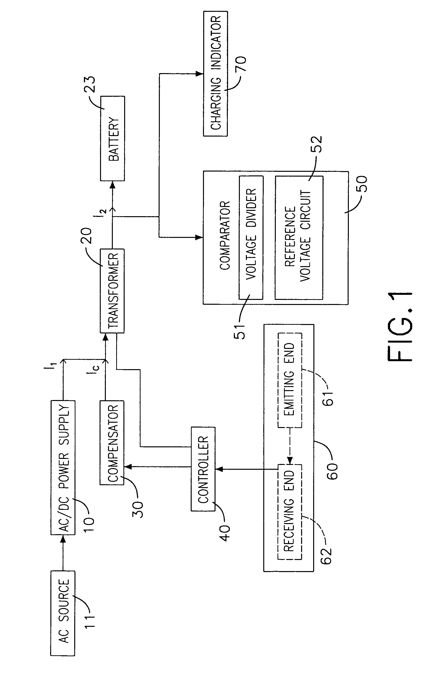
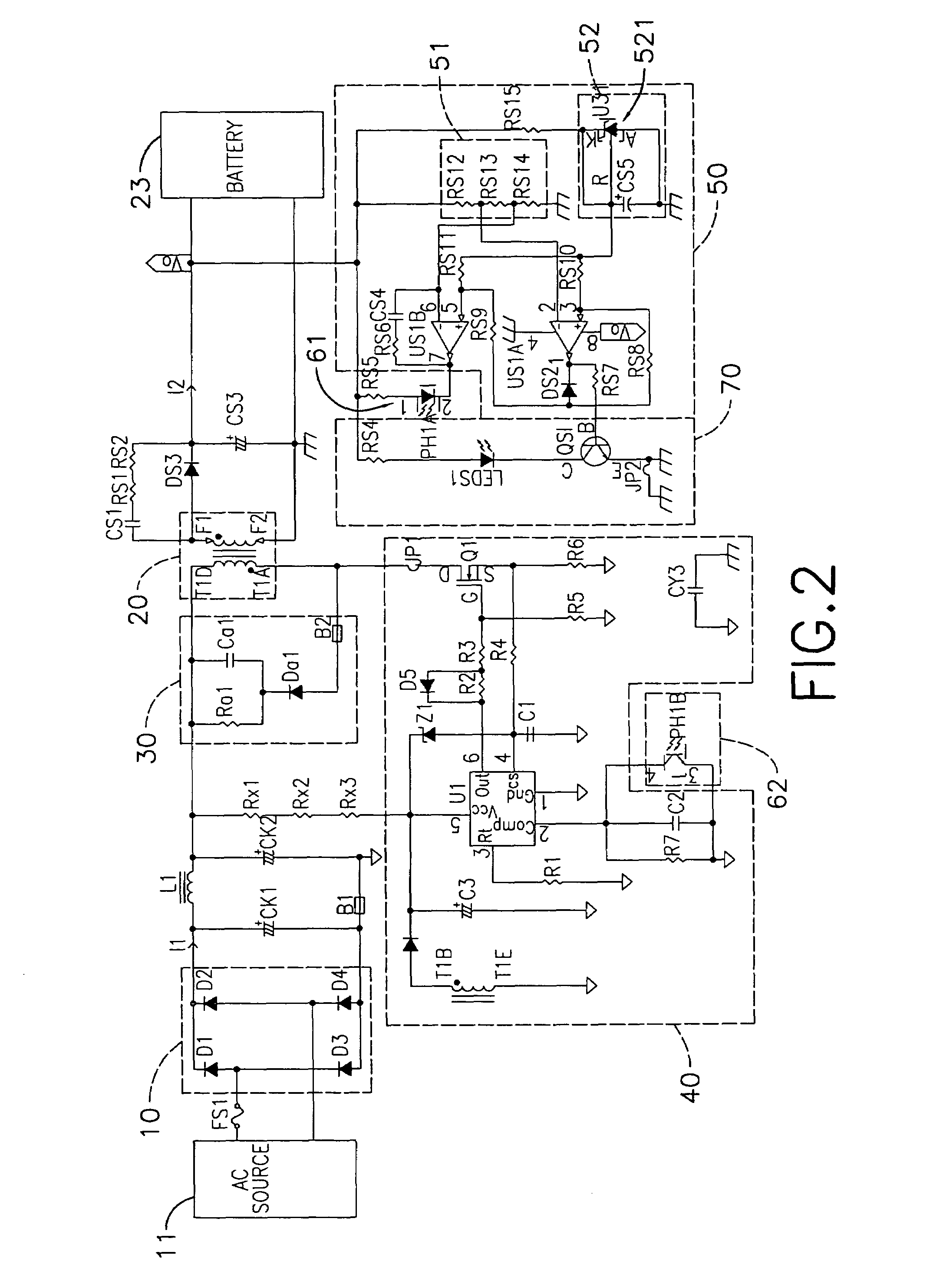
[0019]As shown in FIG. 1, a preferred embodiment of the disclosed two-step charger includes: an AC / DC power supply 10, a transformer 20, a compensator 30, a controller 40, a comparator 50, an isolating controller 60, and a charging indicator 70.

[0020]The AC / DC power supply 10 is connected to an AC source 11 and converts the AC current into a first DC current I1 for output.

[0021]The transformer has a primary side and a secondary side (both not shown). The primary side is connected to the AC / DC power supply 10. The secondary side detects the first DC current I1 and outputs a second DC current I2. The secondary side is connected to a battery 23 in a removable way.

[0022]The compensator 30 is connected to the primary side of the transformer 20 and outputs a compensating current IC to increase the DC current entering the primary side of the transformer 20.

[0023]The controller 40 is connected to the transformer 20 and the compensator 30 to control the compensator 30 in outputting the compe...


PUM

PropertyMeasurementUnit
AC currentaaaaaaaaaa
DC currentaaaaaaaaaa
reference voltageaaaaaaaaaa

Abstract

A two-step charger includes an AC / DC power supply, a transformer, a compensator, a controller, a comparator and an isolating controller. The comparator detects whether a battery is connected to the transformer. If so, a command voltage of the charger is set at a high level. Since the battery voltage is lower than the command voltage, the controller orders the compensator to send out a compensating current. The current entering the primary side of the transformer is increased to promote the output current from the secondary side of the transformer. Once the comparator detects that the battery reaches as high as the charger, the command voltage is adjusted to a low level. The controller orders the compensator to stop outputting the compensating current. Therefore, a larger current can speed up battery charging. Once the battery is fully charged, the charging voltage is lowered to avoid high temperature.

Description

BACKGROUND OF THE INVENTION[0001]1. Field of the Invention[0002]The invention relates to a charger and, in particular, to a two-step charger that can adjust the level of its charging command voltage depending upon the charging status of the battery.[0003]2. Description of Related Art[0004]In view of environmental protection, many objects that cannot be decomposed by nature or cause pollution after they are decomposed are phasing out. For example, non-rechargeable batteries contain materials harmful to the environment. Therefore, rechargeable batteries become more popular nowadays. With an appropriate charger, the rechargeable batteries can be repeatedly used.[0005]Most of the chargers on the market have the function of two-step charging. That is, they allow the user to decide whether to charge the batteries at a normal speed or a faster speed. The so-called quick charging refers to the charging with a larger current. Although this method can finish charging in a shorter time, people...

Claims


Application Information

Patent Timeline
Patent Type & Authority Patents(United States)
IPC IPC(8): H02J7/16G05F1/00H01F27/42H01F38/00H02J7/06H02M1/00H02M3/335H02M7/5383
CPCH02J7/0047H02J7/045H02J7/06H02J7/04H02J7/007182H02J7/0049
Inventor LAI, YU-CHILIAO, JI-SHUN
Owner ASIAN POWER DEVICES
Learn More