Lighter

a technology of lighter and cigarette lighter, which is applied in the field of lighters, can solve the problems of not being practical for lightening a cigarette, the lighter cannot effectively lighten the candle, and the single ignition angle of the piezoelectric lighter, so as to facilitate the practical use of the lighter, reduce the manufacturing cost of the lighter, and facilitate the effect of lightening

Inactive Publication Date: 2006-12-14
LUO XIN WEN
View PDF1 Cites 17 Cited by
  • Summary
  • Abstract
  • Description
  • Claims
  • Application Information

AI Technical Summary

Benefits of technology

[0012] Another object of the present invention is to-provide a lighter, wherein the pivot movement of the pivot nozzle is controlled through a gear unit such that the tilt angle of the pivot nozzle can be adjustably locked up through the gear unit.
[0013] Another object of the present invention is to provide a lighter, which does not require to alter the original structural design of the lighter so as to minimize the manufacturing cost of the lighter incorporating with the pivot nozzle.
[0014] Another object of the present invention is to provide a lighter, wherein no expensive or complicated mechanism is required to employ in the piezoelectric lighter, so that the present invention successfully provides an economic and efficient solution not only for allowing the pivot nozzle to be pivotally fold to adjust the tilt angle of the lighter but also for facilitating the practical use of the lighter.

Problems solved by technology

However, such piezoelectric lighter has a major drawback that such piezoelectric lighter can provide a single ignition angle.
Since the gas is upwardly ejected from the gas nozzle, the lighter cannot effectively lighten the candle when the lighter is in such slanted position.
However, such lighter is not practical use for lightening a cigarette.
However, the utility lighter is bulky that the user is unable to carry the utility lighter in his or her pocket.
In addition, during the movement of the gas nozzle, the ignition tip of the piezoelectric unit may be forced to misalign with the gas nozzle which will cause the malfunction of the piezoelectric lighter.

Method used


Image

  • Lighter
  • Lighter
  • Lighter

Examples


Embodiment Construction

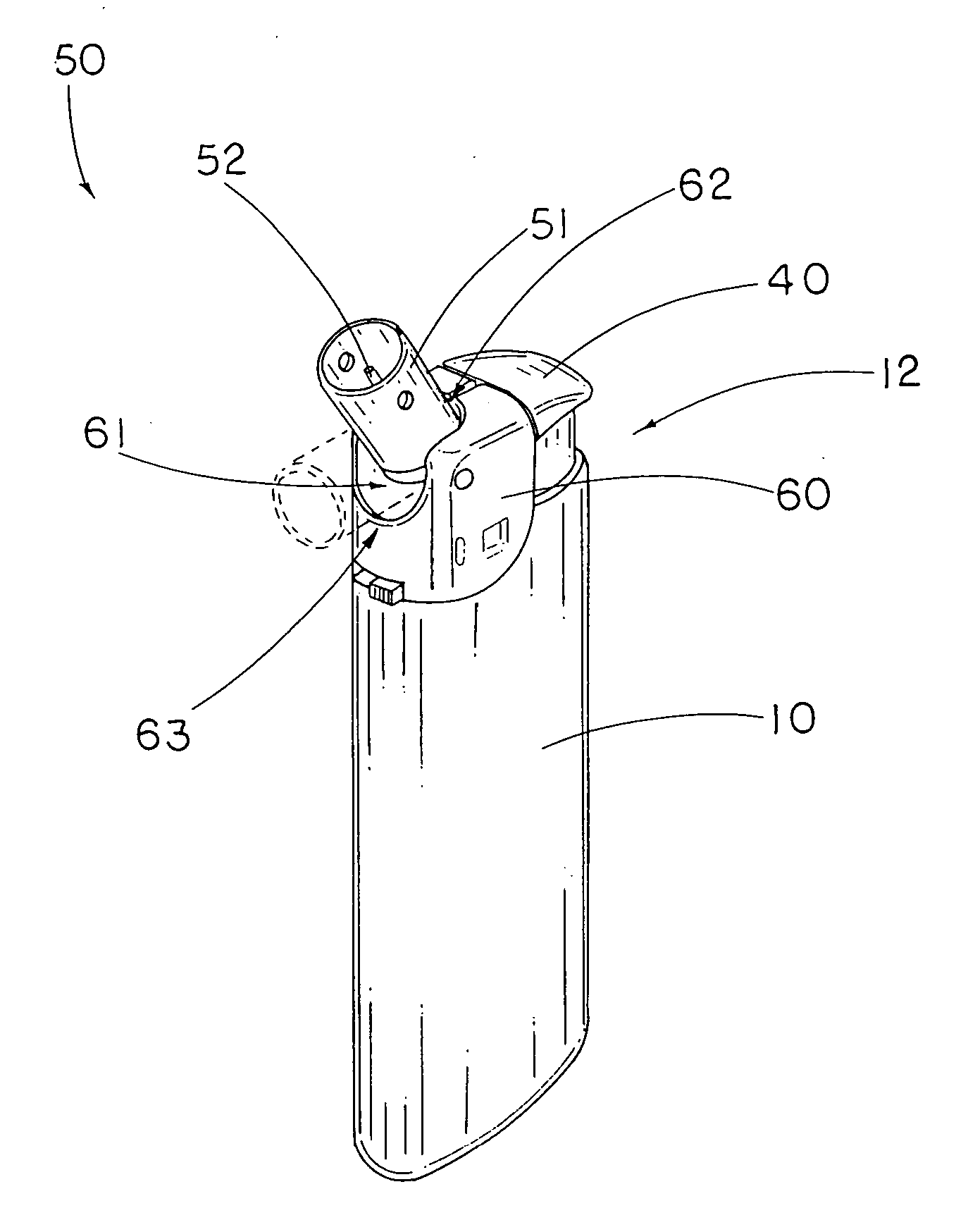
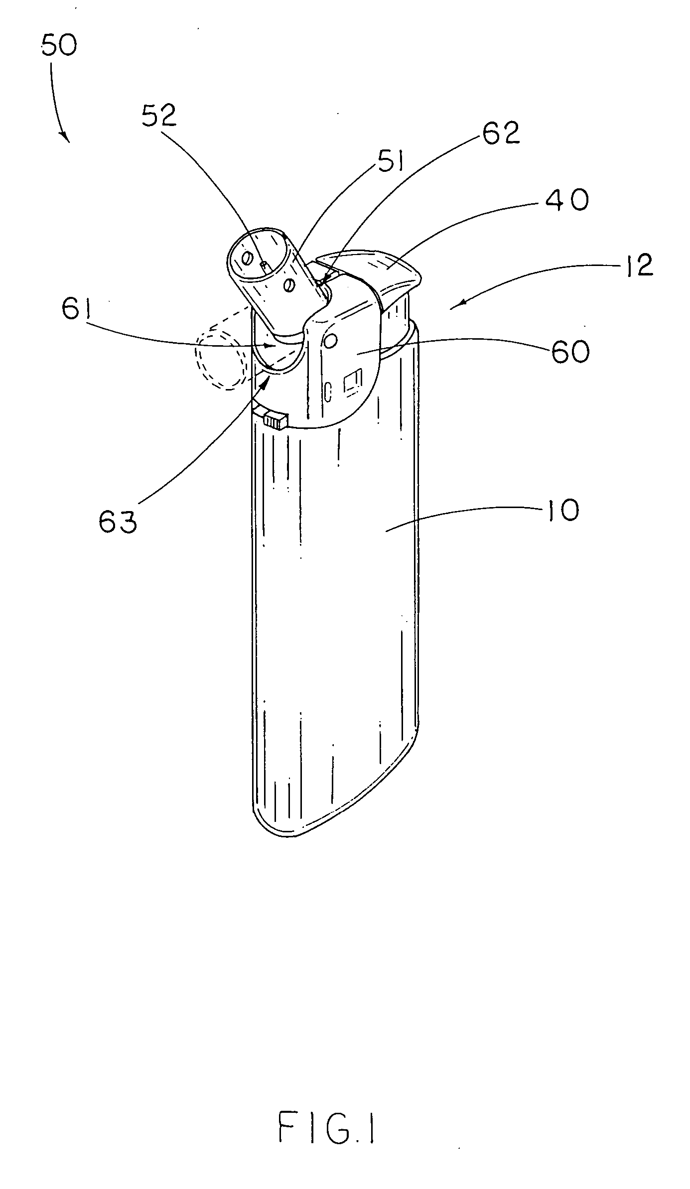
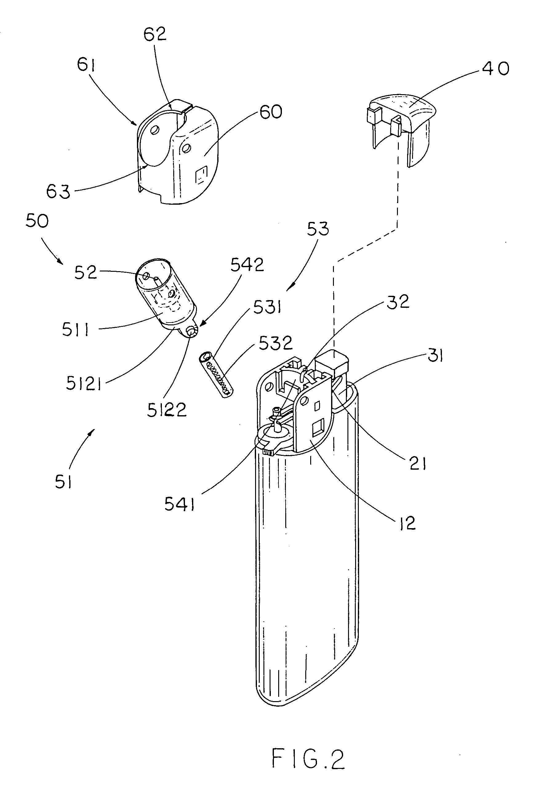
[0029] Referring to FIGS. 1 through 3 of the drawings, a lighter according to a preferred embodiment of the present invention is illustrated, wherein the lighter comprises a lighter casing 10 having a gas liquefied storage 11 and comprising a top supporting frame 12, and a gas valve 20 received in the lighter casing 10 and communicating with the liquefied gas storage 11 for controlling a flow of gas therefrom.

[0030] The lighter further comprises a piezoelectric unit 30, an ignition button 40 and a pivot nozzle unit 50.

[0031] The piezoelectric unit 30, which is disposed in the lighter casing 10 for generating piezoelectricity, comprises a movable operating part 31 extended upwardly and an ignition tip 32 arranged when the movable operating part 31 is depressed downwardly, sparks are generated from the ignition tip 32.

[0032] The ignition button 40 is slidably mounted to the top supporting frame 12 of the lighter casing 10 to depress the movable operating part 31 of the piezoelectri...


PUM


Abstract

A lighter includes a pivot nozzle including a nozzle housing pivotally mounted at a lighter casing, a gas nozzle substantially supported in the nozzle housing in a stationary manner, and a retention skeleton having a predetermine flexibility is extended from a gas valve to the gas nozzle for guiding the gas emitting from a liquefied gas storage to the gas nozzle, wherein the nozzle housing is pivotally folded with respect to the lighter casing to selectively adjust a tilt angle of the gas nozzle while the retention skeleton retains the gas flowing towards the gas nozzle such that when the ignition button is depressed to depress the piezoelectric unit and to release the gas at the gas valve at the same time, the gas is emitted at the gas nozzle through the retention skeleton and is ignited by the sparks at the ignition tip of the piezoelectric unit.

Description

BACKGROUND OF THE PRESENT INVENTION [0001] 1. Field of Invention [0002] The present invention relates to a lighter, and more particularly to a lighter which comprises a pivot nozzle pivotally connected to a lighter casing to selectively adjust a tilt angle of the pivot nozzle with respect to the lighter casing for ignition. [0003] 2. Description of Related Arts [0004] Generally, a conventional lighter, such as a piezoelectric lighter, comprises a lighter casing having a liquefied fuel storage, a gas nozzle extended to a ceiling of the lighter casing and communicating with the liquefied fuel storage for controlling a flow of gas, a piezoelectric unit disposed in the lighter casing for generating sparks when the piezoelectric unit is depressed, and an ignition button slidably mounted on the lighter casing and arranged when the ignition button is depressed downwardly, the piezoelectric unit is depressed while the gas is released from the liquefied fuel storage to the gas nozzle and is ...

Claims


Application Information

Patent Timeline
Patent Type & Authority Applications(United States)
IPC IPC(8): F23Q2/00
CPCF23Q2/287F23Q2/163
Inventor LUO, XIN WEN
Owner LUO XIN WEN
Why Eureka
Try Eureka