Gage for measuring diameters
a technology of gages and diameters, applied in the field of measuring gages, can solve problems such as measurement differences, and achieve the effect of low heat transfer coefficien
- Summary
- Abstract
- Description
- Claims
- Application Information
AI Technical Summary
Benefits of technology
Problems solved by technology
Method used
Image
Examples
Embodiment Construction
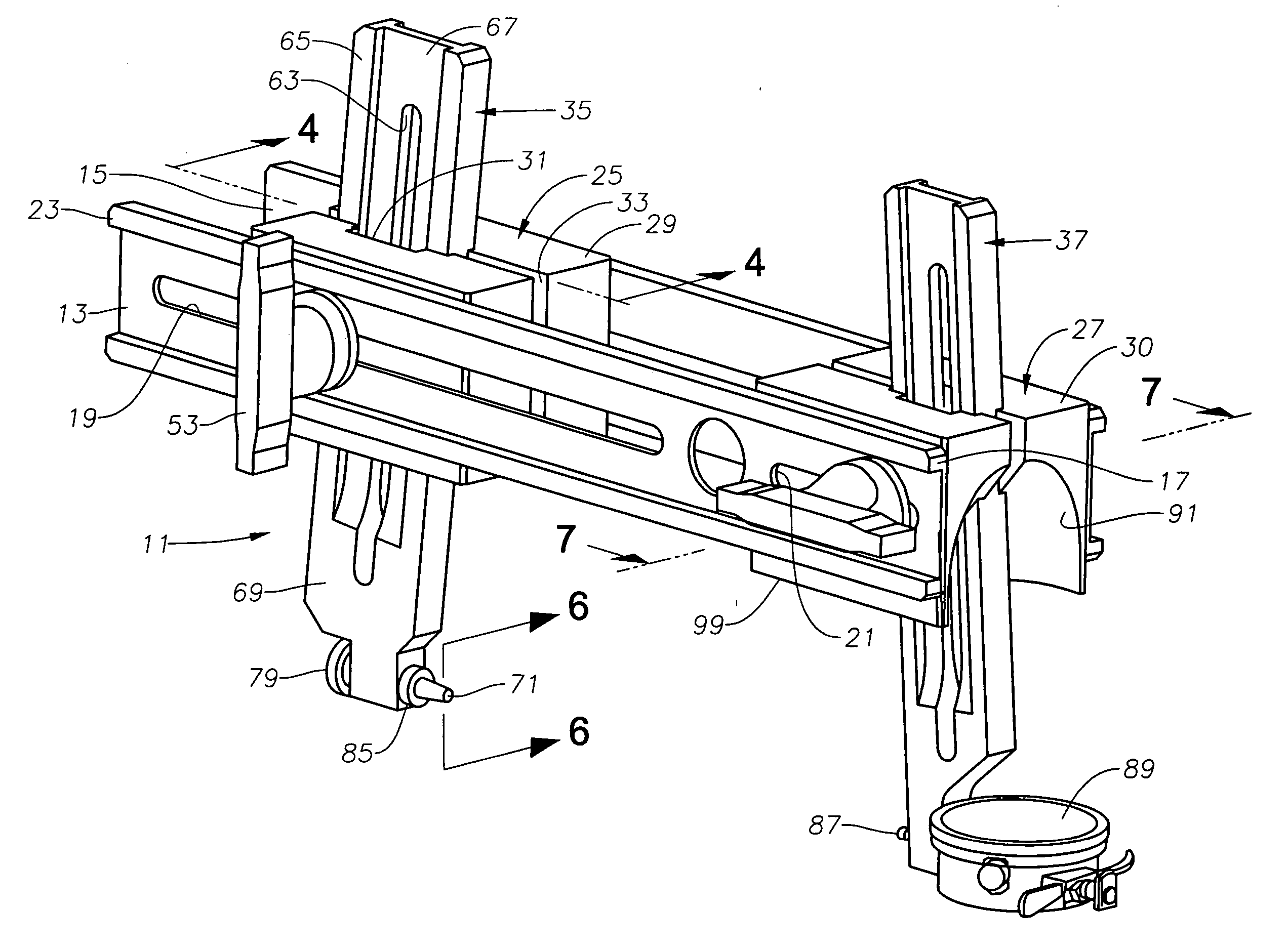
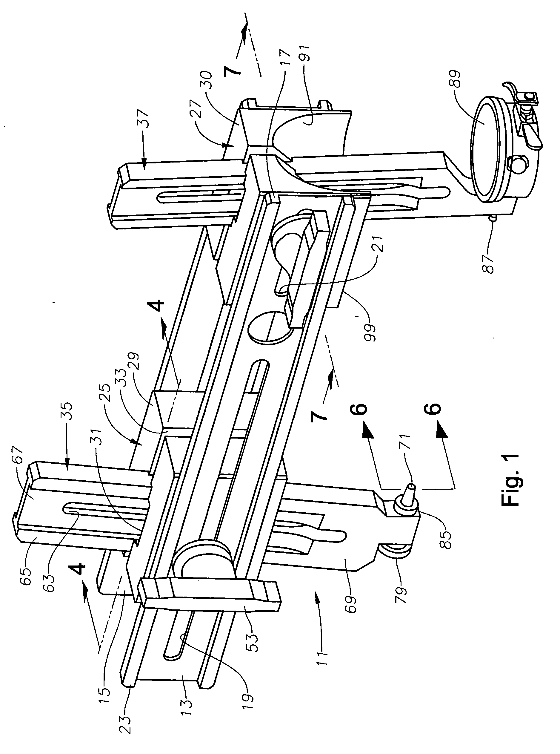
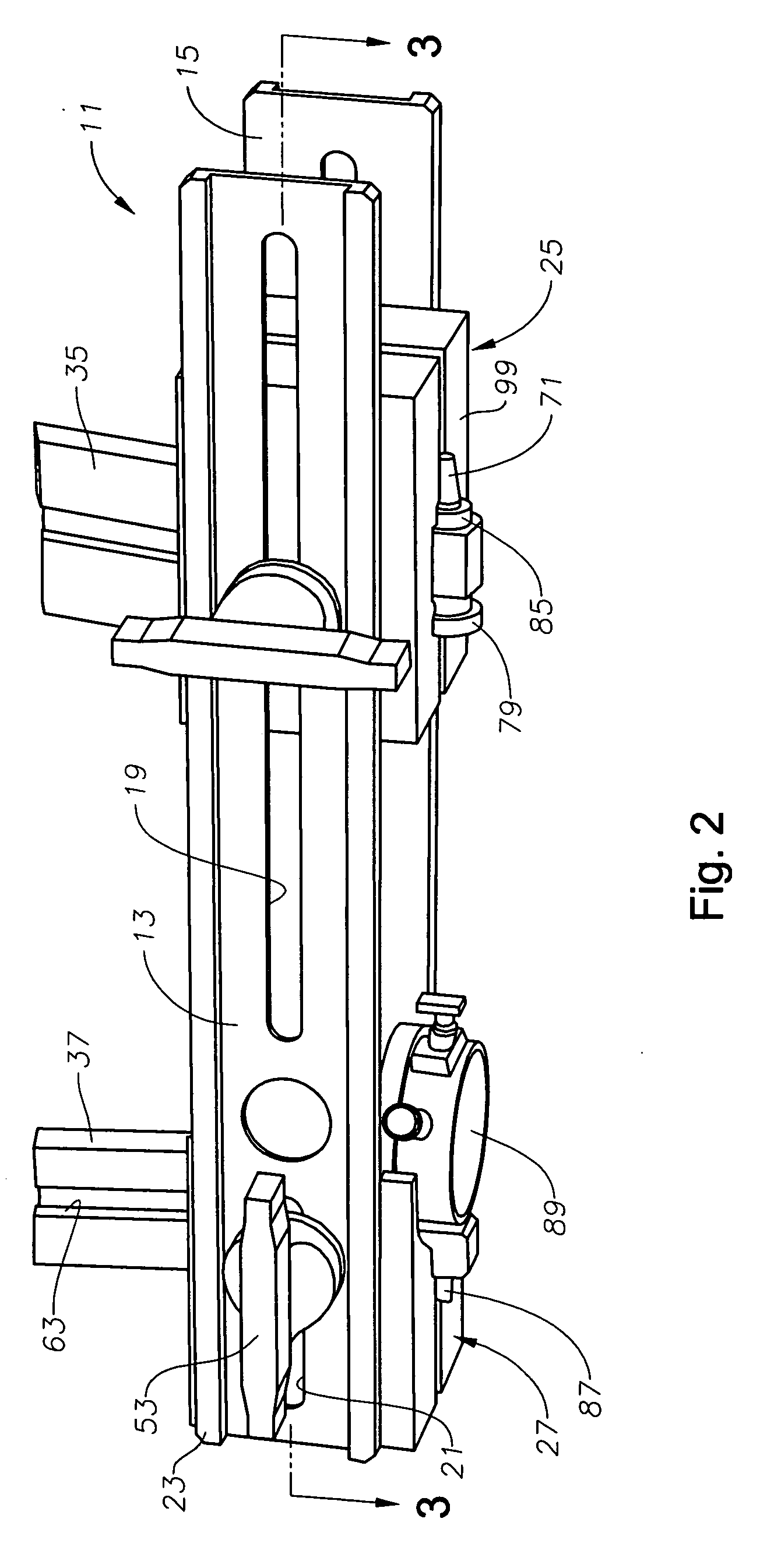
[0020] Referring to FIG. 1, gage 11 has a pair of side rails 13, 15, preferably formed of metal, such as steel. Side rails 13, 15 are mirror images of each other, parallel to each other, and spaced apart from each other. Each side rail 13, 15 is a generally flat rectangular bar with flanges 17 at its upper and lower edges. In cross section as shown in FIGS. 5 and 7, each side rail 13, 15 are in the form of a C-Beam. Each side rail 13, 15 has a width measured from the upper side of one flange 17 to the lower side of its other flange 17 that is greater than its thickness. When gage 11 is oriented as shown in FIG. 1, the width is in a vertical plane.
[0021] Each side rail 13, 15 have a pair of adjusting slots 19, 21. Slots 19, 21 are elongated holes or slots that extend parallel to the length or longitudinal axis of each side rail 13, 15. In this embodiment, slot 19 has a much greater length than slot 21 although they could be the same length. Alternately, slots 19, 21 could be a serie...
PUM
 Abstract
Description
Claims
Application Information
 - R&D
- Intellectual Property
- Life Sciences
- Materials
- Tech Scout
- Unparalleled Data Quality
- Higher Quality Content
- 60% Fewer Hallucinations
Browse by: Latest US Patents, China's latest patents, Technical Efficacy Thesaurus, Application Domain, Technology Topic, Popular Technical Reports.
© 2025 PatSnap. All rights reserved.Legal|Privacy policy|Modern Slavery Act Transparency Statement|Sitemap|About US| Contact US: help@patsnap.com


