Elevating load platforms

a technology of lifting platform and lifting frame, which is applied in the direction of lifting frame, variable height table, lifting device, etc., can solve the problems of needing a variety of springs and special dangers of manual loading and unloading of pallets

Inactive Publication Date: 2006-12-21
AMIATA HLDG
View PDF7 Cites 12 Cited by
  • Summary
  • Abstract
  • Description
  • Claims
  • Application Information

AI Technical Summary

Benefits of technology

[0006] According to one aspect of the present invention there is provided an elevating load platform comprising a base member and a load supporting member interconnected by a linkage that facilitates vertical movement of the load supporting member generally parallel to the base member, and a plurality of coil springs positioned to urge the load supporting member upwardly relative to the base member so that when the load supporting member is laden the coil springs are compressed, and as the load is progressively removed the coil springs urge the load supporting member upwards to thereby maintain the load supporting member at a desired height, the linkage means comprising a pair of spaced scissor linkages interconnected by a central cross-member the plurality of compression springs being positioned in a spaced array interposed between the base member and the cross-member.
[0007] Preferably, the cross-member and the base member include spring support means that support the springs in use but facilitate simple removal and replaceability of the springs.
[0014] In a preferred embodiment the platform includes means to urge that end of each scissor linkage along the rail to lift the cross-member so that end of the linkage can be released from the rail to allow the load supporting member to be lifted to such a height that the springs become disengaged from the spring support means thereby facilitating replacement.

Problems solved by technology

The manual loading and unloading of pallets is particularly dangerous from the point of view of back injury, particularly when the operators must lift a load bending down to the base of a pallet.
An issue with load elevators of the kind described in the earlier patents is the need to have a variety of sets of springs that have to be changed as the load is changed.

Method used


Image

  • Elevating load platforms
  • Elevating load platforms
  • Elevating load platforms

Examples


Embodiment Construction

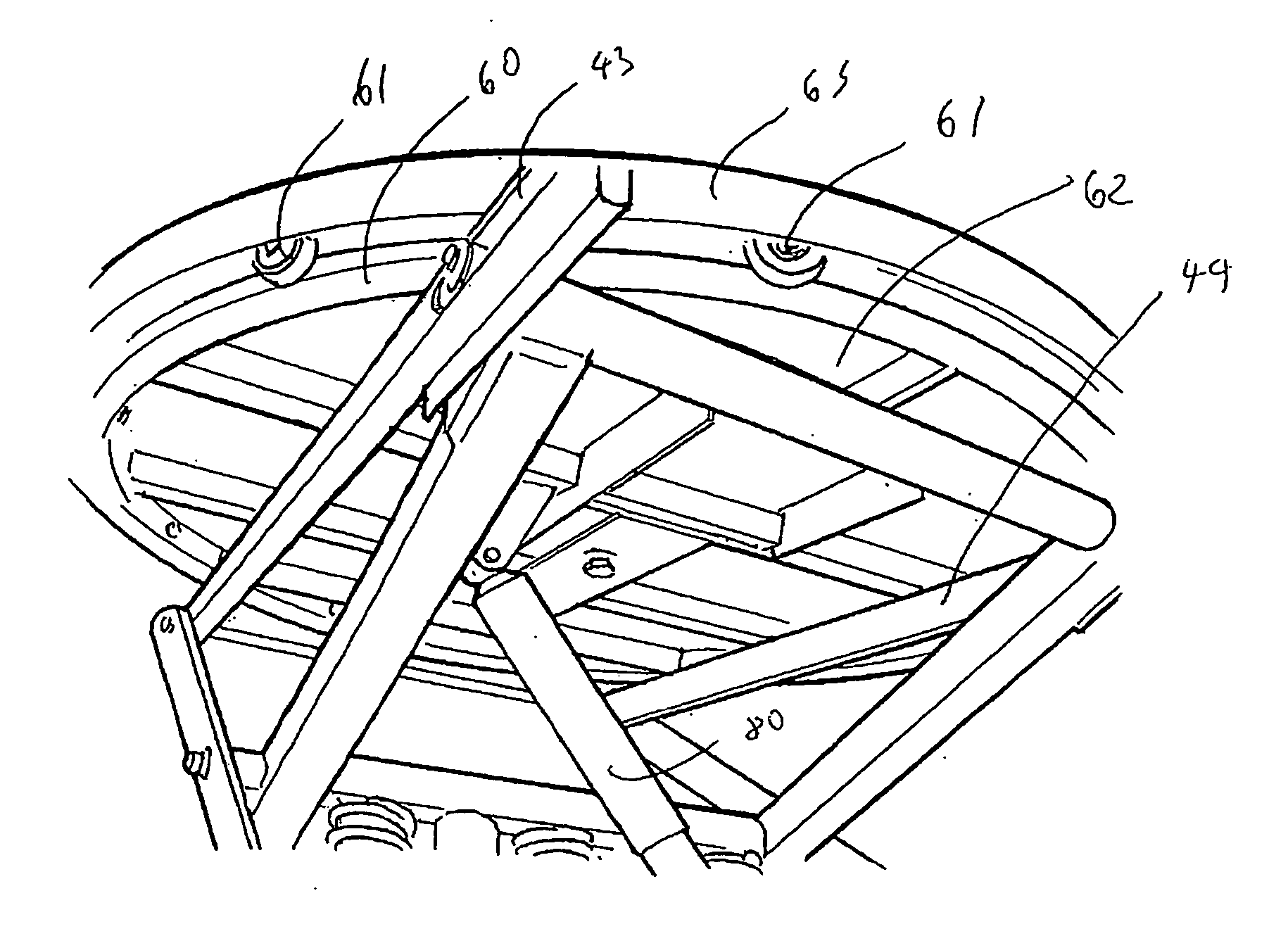
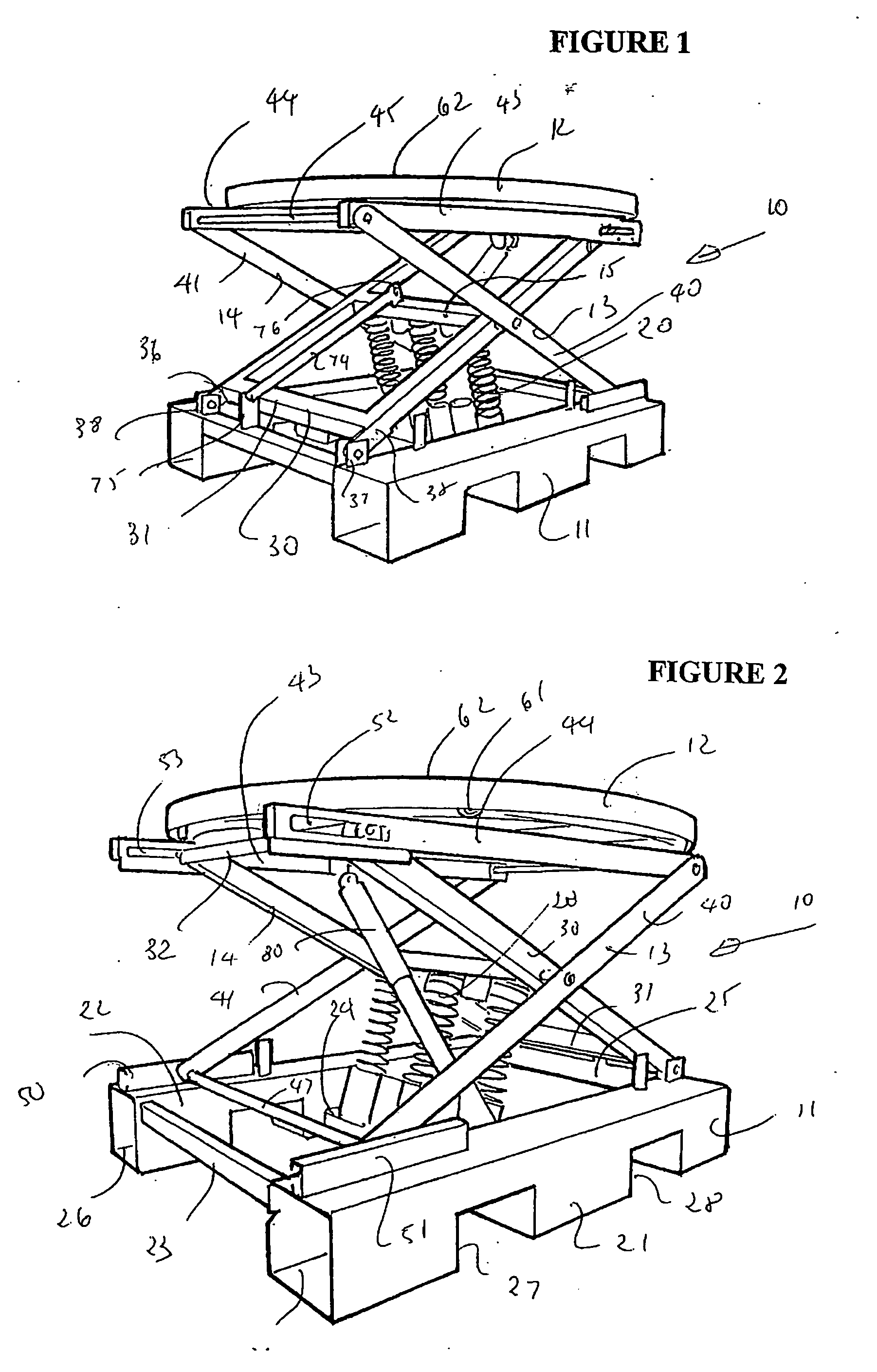
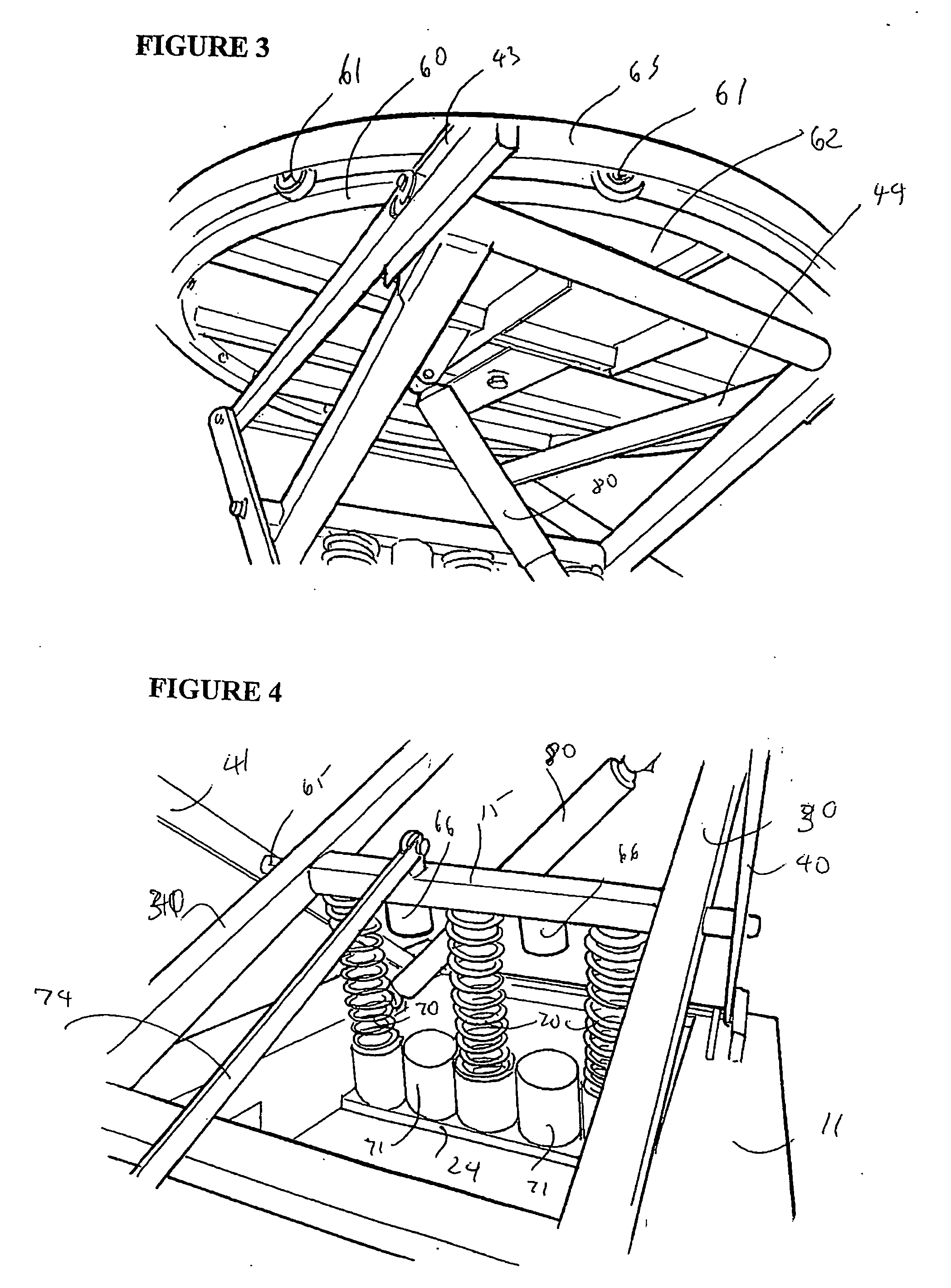
[0022] As shown in the accompanying drawings, an elevating load platform 10 comprises a base structure 11 that supports a load supporting platform 12. The base support and load support platform are interconnected by scissor linkages 13, 14 that are mounted to extend along two parallel sides of the platform. The scissor linkages 13, 14 are joined by a central cross-member 15 and an array of coil springs 20 are positioned between the base structure 11 and the underside of the cross-member 15 the scissor linkages 13, 14 and the coil springs 20 operate to urge the load supporting platform 12 upwardly parallel to the base structure 11.

[0023] The base structure 11 is fabricated from steel and can provide two elongate parallel spaced bearers 21, 22 joined by cross-members 23, 24, 25. The elongate bearers 21, 22 define forklift tine entry 26 at either end. The elongate bearers also have rectangular cutouts 27, 28 along their sides defining forklift tine entry from opposite sides. Thus, the...


PUM


Abstract

An elevating load platform comprising a base member and a load supporting member interconnected by a linkage means that facilitates vertical movement of the load supporting member generally parallel to the base member, and a plurality of coil springs positioned to urge the load supporting member upwardly relative to the base member so that when the load supporting member is laden the coil springs are compressed, and as the load is progressively removed the coil springs urge the load supporting member upwards to thereby maintain the load supporting member at a desired height, the linkage means comprising a pair of spaced scissor linkages interconnected by a central cross-member, the plurality of compression springs being positioned in a spaced array interposed between the base member and the cross-member.

Description

INTRODUCTION [0001] This invention relates to elevating load platforms, and in particular load platforms for use with palletised loads. [0002] These days health and safety requirements place considerable emphasis on the need to protect operators from back injuries. The manual loading and unloading of pallets is particularly dangerous from the point of view of back injury, particularly when the operators must lift a load bending down to the base of a pallet. [0003] There have thus been a number of proposals to ensure that the height of the load that is to be lifted in either a loading or unloading situation is at an optimum level. It is known to use electric or hydraulic means to raise and lower the platform and maintain it at the optimum height. [0004] In Australian patents 571354 and 582692 it was suggested to use sets of coil springs calibrated in dependence of the load to again ensure that the platform is substantially at the optimum height as the platform is loaded or unloaded. ...

Claims


Application Information

Patent Timeline
Patent Type & Authority Applications(United States)
IPC IPC(8): B66B9/02
CPCB66F7/08B66F7/065
Inventor PATTEN, SIDNEY A.MUNRO, DAVID M.
Owner AMIATA HLDG
Why Eureka
Try Eureka