[0007]Accordingly, a primary object of the present invention is to provide a tin tag supply device having improved guide means for guiding the gun-attached operating member during the displacement thereof relative to the tin tag housing as the nailing gun is displaced toward and away from the work during repeated nailing operation.
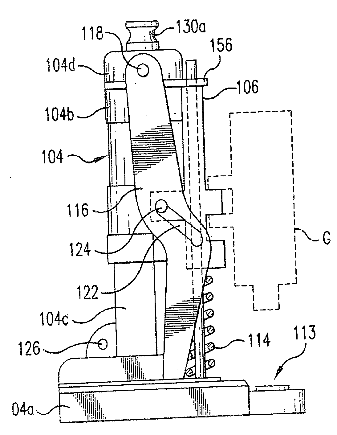
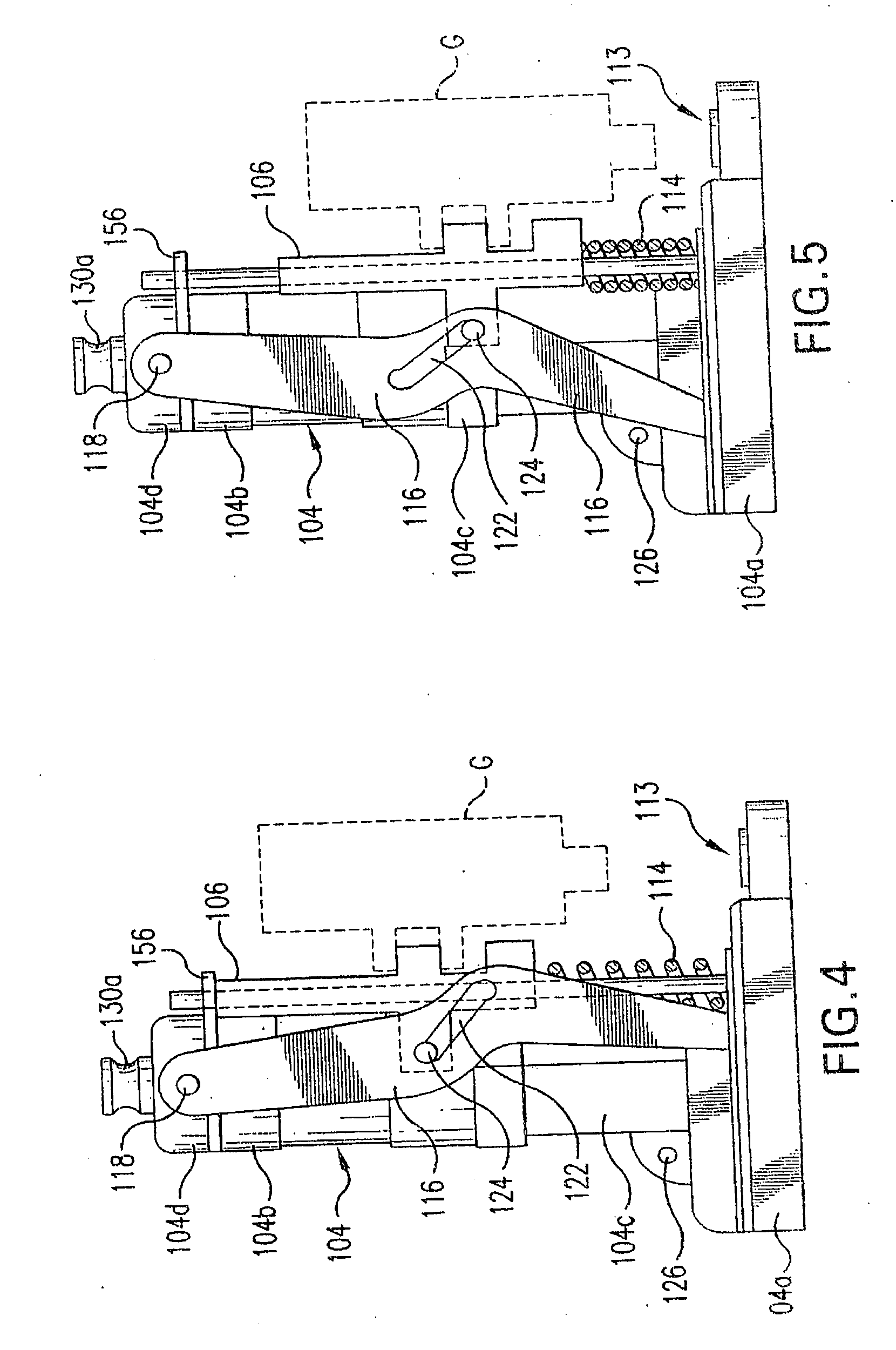
[0008]A more specific object of the invention is to provide guide means including a pair of parallel vertical guide rods that extend through corresponding through bores contained in an operating member that is formed from a hard synthetic plastic material. One end of the operating member is provided with a first projection that is adapted for connection with the nailing gun. The other end of the operating member is provided with a pair of horizontally spaced second projections that are provided with
cam pins that extend laterally outwardly from the second projections into
cam slots contained in the levers that operate the reciprocatory shuttle means to displace a tin tag from the bottom of a stack and to transport the removed tin tag toward the nailing station. The upper ends of the levers are pivotally connected with the upper cap portion of the body portion of the attachment tool, and the lower ends of the guide rods are fastened to the horizontal base portion of the tool body. Preferably, oil-impregnated tubular bearings of
bronze or
brass are mounted within the through bores of the operating member concentrically about the guide rods, thereby to lubricate the rods to improve the sliding movement of the operating member.
[0010]Preferably, the operating member is formed from a hard synthetic plastic material, such as 6619 nylon, a 66% nylon / 33% glass composition. The improved guide means eliminates side-to-side sway, produces little wear factor of the synthetic plastic material, and results in two dissimilar materials riding as a
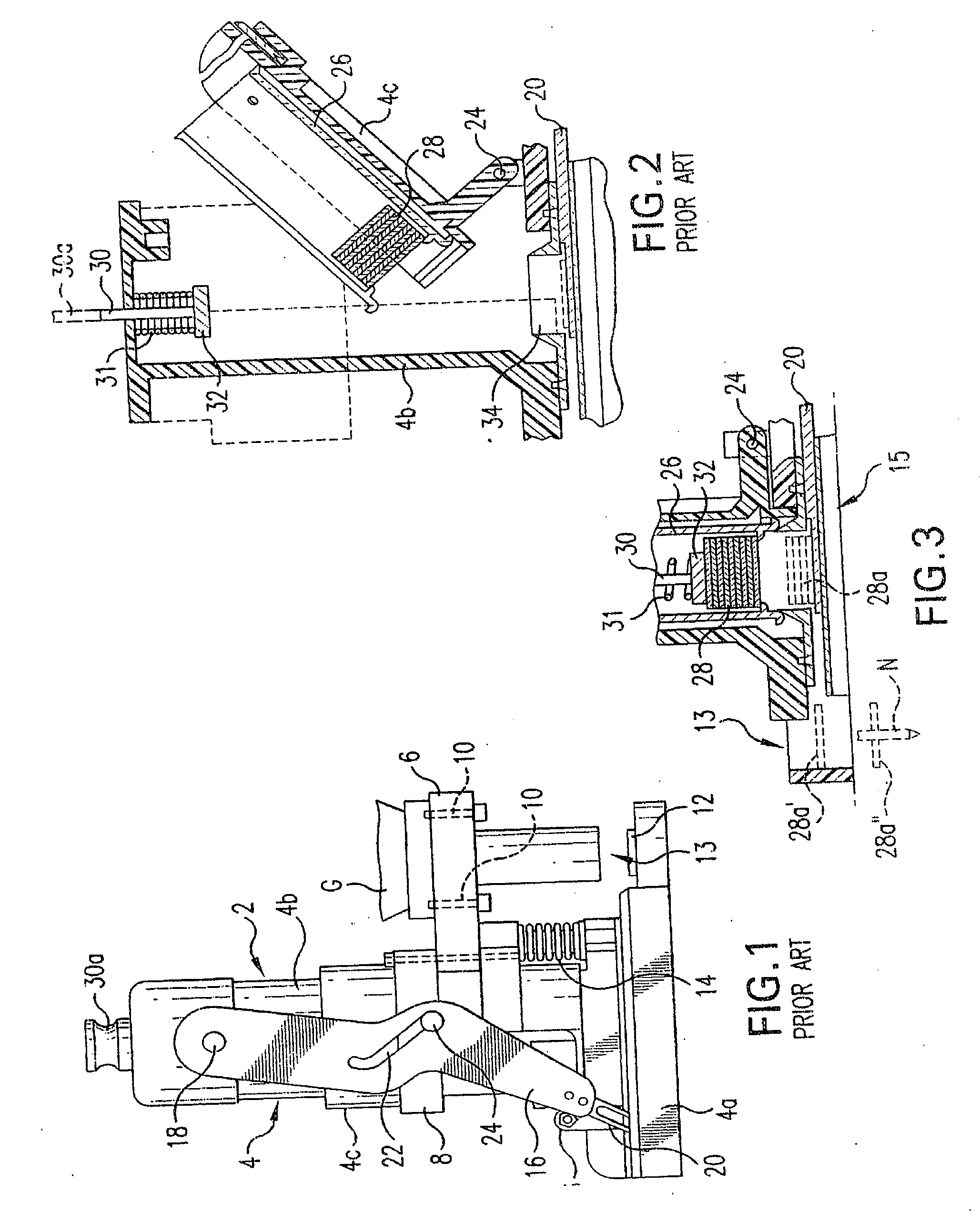
bearing surface. The original prior art guide means generated significant friction, with subsequent premature wear of the molded plastic components, thereby reducing the life of the tool. Because of the excess friction, the application of additional lubricating oil was required at regular intervals to hold the excessive wear of the molded plastic components to an
absolute minimum.
[0011]The new improved
vertical motion of the
metal cam is designed and created through a redesigned plastic sliding
mount with inserted
bronze bushings, which are permanently oil-saturated for
lubrication at manufacture. The two independent parallel bushings slide on polished chrome shafts attached and fixed to the base and cap housing components, thereby resulting in significantly reduced
contact friction and wear through permanent
lubrication from the oil-saturated bearings.
[0012]The stainless
steel piston of the prior art is replaced by a shuttle plate member that is formed from resilient tempered steel that retains the memory characteristics necessary and provides jam-free operation. The
spring steel shuttle plate allows for flexing under the tin tags when shuttling to the loading position, and when the tin tag is shuttled to the firing position, the punched out tongue springs upward to position a tin tag and provides vertical movement. The prior art
piston design carried the entire stainless hardware plate along with the tin tag itself to the firing position for every shot. The new design pushes the tin tag to the firing position which results in moving much less hardware, produces reduction in weight, and allows for a much more efficient operation.
[0013]The body portion of the tool housing includes a
top cap section that is arranged above a horizontal support plate that includes a marginal portion containing openings that receive the upper ends of the stainless steel guide rods. The operating member is spring biased upwardly into engagement with the horizontal support plate when the operating member is in its initial retracted position. Owing to the improved shuttle plate design, the recess of the plates avoid the roofing
tar buildup on the tool that is always a problem during extend use in
hot weather. With the plastic now riding and contacting the roofing paper instead of the
metal plates, the problem of buildup is significantly reduced if not eliminated. in damp or extremely
hot weather conditions, the roofing paper becomes very sticky and can create a severe problem with build-up. The roofing paper
tar does not adhere to the redesigned synthetic plastic base.

