Liquid ejection head, liquid ejection apparatus, and manufacturing method of liquid ejection head

a technology of liquid ejection head and manufacturing method, which is applied in the direction of combustion process, combustion type, burner, etc., can solve the problems of insufficient adhesive surface force, limited material selection space, adhesive permeation and movement, etc., and achieve excellent productivity and improve image quality.

Inactive Publication Date: 2006-12-21
SONY CORP
View PDF0 Cites 20 Cited by
  • Summary
  • Abstract
  • Description
  • Claims
  • Application Information

AI Technical Summary

Benefits of technology

[0028] Accordingly, it is desirable to provide a liquid ejection head, a liquid ejection apparatus, and a manufacturing method of the liquid ejection head capable of achieving a necessary adhesive strength and adhesive uniformity with a pressure within a suitable range without anxiety over damage and also being capable of corresponding to the improvement of image quality due to miniaturizing liquid droplets as well as being excellent in productivity.
[0029] Furthermore, it is also desirable to provide a cleaning device of a liquid ejection head capable of securely removing ink and contaminants adhered to the liquid ejection head as well as ensuring the life of the product.

Problems solved by technology

When bonding the nozzle sheet 306 made of such a material on the barrier layer 303, an insufficient adhesive surface force becomes a problem.
However, regarding to the item (1), materials available for the barrier layer 303 are extremely limited, so that there is scarce room for selecting the material.
Thus, the means of items (4) and (3) remain for improvement in structure; however, there are problems presently as follows.
First, in the flatness of the adhesive surface during general bonding, a liquid adhesive with flowability is sandwiched between the surfaces, so that although the flatness has a slight problem, the adhesive permeates and moves when the surfaces are pressurized during bonding.
As a result, the clearances due to the insufficient flatness of the adhesive surface are absorbed as thickness unevenness of the adhesive.

Method used


Image

  • Liquid ejection head, liquid ejection apparatus, and manufacturing method of liquid ejection head
  • Liquid ejection head, liquid ejection apparatus, and manufacturing method of liquid ejection head
  • Liquid ejection head, liquid ejection apparatus, and manufacturing method of liquid ejection head

Examples


Embodiment Construction

[0060] Embodiments of the present invention for solving the problems described above will be described below with reference to the drawings.

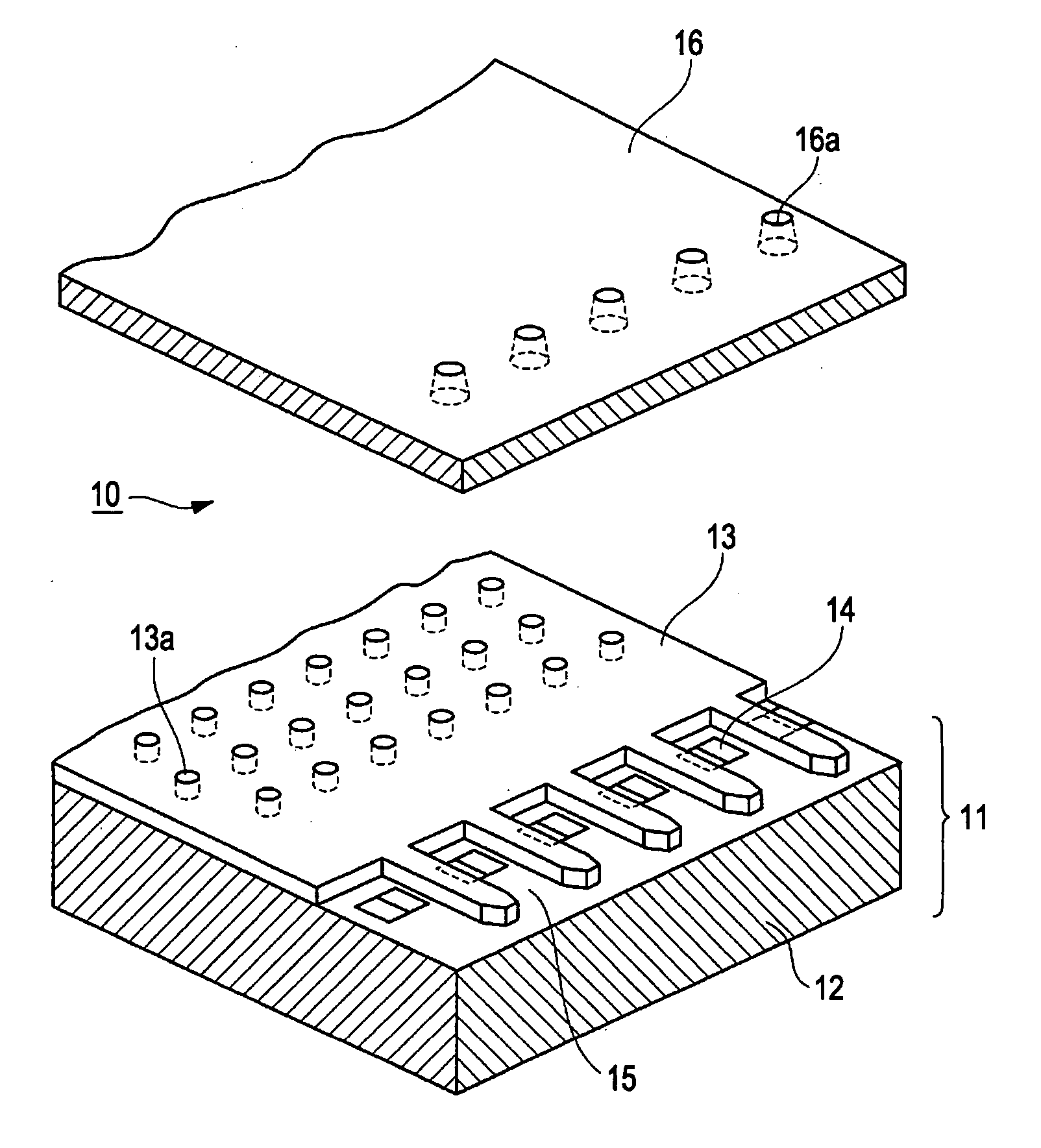
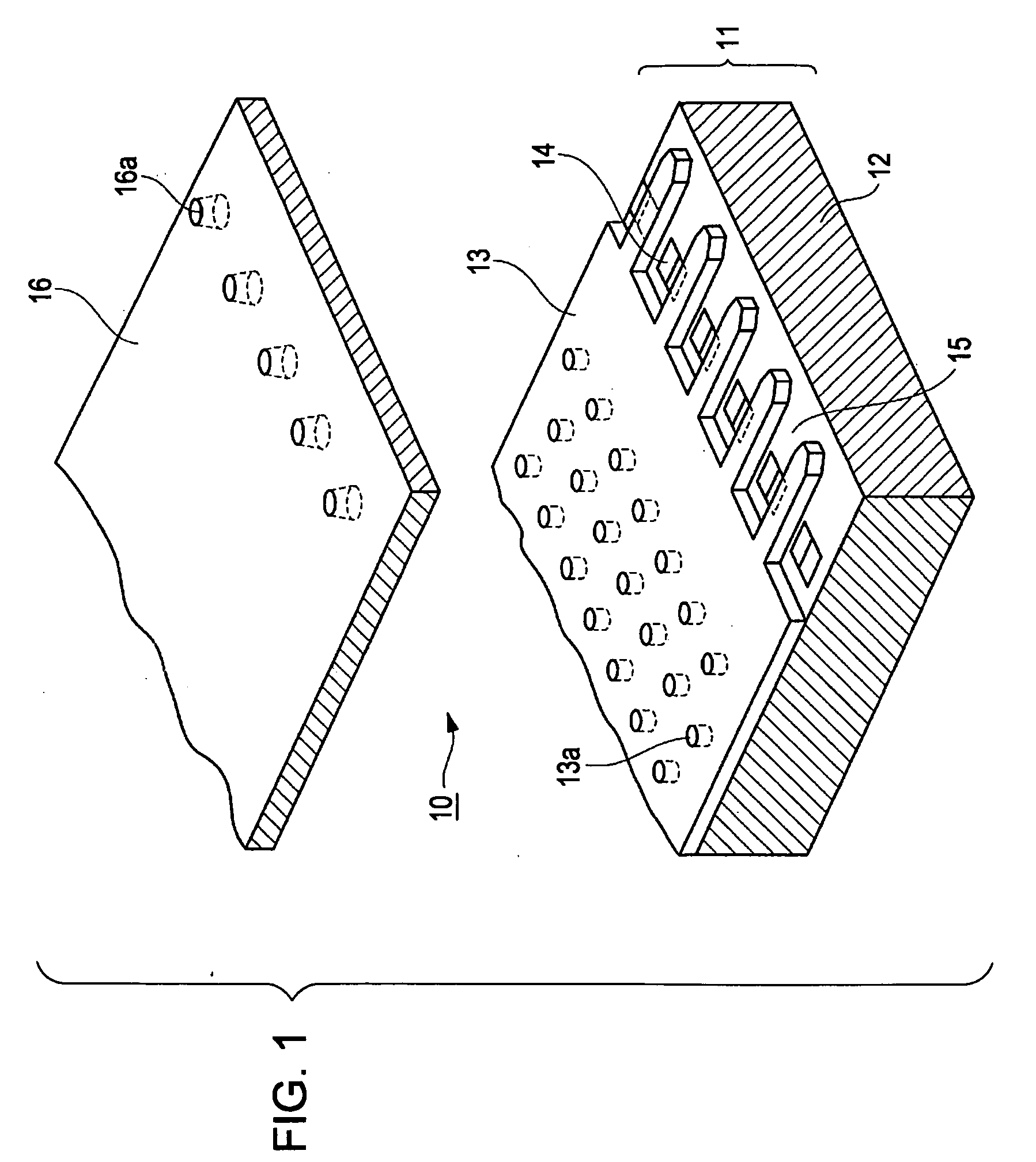
[0061] A liquid ejection head according to the present invention is equivalent to a head 10 of an inkjet printer according to an embodiment below-mentioned. According to the embodiment, the liquid ejected from the head 10 is ink; a liquid chamber for containing ink is an ink chamber 15; and the micro amount (several pico litters, for example) of the ink ejected from a nozzle 16a is an ink droplet. Furthermore, according to the embodiment, a heating element 14 is used as an energy generating element. The heating element 14 is precipitated on one face of a semiconductor substrate 12 to form one face (bottom wall) of the ink chamber 15. A liquid ejection apparatus according to the present invention is equivalent to a thermal inkjet printer having such a head 10 according to the embodiment.

[0062]FIG. 1 is a partial perspective view of the head 10 ...


PUM


Abstract

A liquid ejection head includes an energy-generating element arranged on a semiconductor substrate, a barrier layer deposited on the semiconductor substrate for forming a liquid chamber in the periphery of the energy-generating element, and a nozzle sheet bonded on the barrier layer and having a nozzle formed at a position opposing the energy-generating element, in which the liquid ejection head ejects liquid contained in the liquid chamber from the nozzle as liquid droplets by the energy-generating element, and the barrier layer is provided with a plurality of depressions, each having an independent contour, arranged within a range, which is separated from the border of the barrier layer, on an adhesive region adhering to the nozzle sheet.

Description

CROSS REFERENCES TO RELATED APPLICATIONS [0001] The present invention contains subject matter related to Japanese Patent Application JP 2005-162340 filed in the Japanese Patent Office on Jun. 02, 2005, JP 2005-237000 filed in the Japanese Patent Office on Aug. 17, 2005, and JP 2005-248291 filed in the Japanese Patent Office on Aug. 29, 2005, the entire contents of which are incorporated herein by reference. BACKGROUND OF THE INVENTION [0002] 1. Field of the Invention [0003] The present invention relates to a liquid ejection head for ejecting liquid within liquid chamber as liquid droplets by an energy generating element, a liquid ejection apparatus, and a manufacturing method of the liquid ejection head, and in particular it relates to a technique for improving the overall adhesion force of a nozzle sheet having nozzles formed thereon. [0004] 2. Description of the Related Art [0005] A liquid ejection apparatus represented by an inkjet printer generally includes a liquid ejection hea...

Claims


Application Information

Patent Timeline
Patent Type & Authority Applications(United States)
IPC IPC(8): B05B1/08B05B15/02
CPCB41J2/14024B41J29/02B41J2/1623B41J2/1603
Inventor EGUCHI, TAKEOONO, SHOGOTAKENAKA, KAZUYASUNAKAMURA, ATSUSHIIKEMOTO, YUICHIROHIRASHIMA, SHIGEYOSHINAKAYAMA, ATSUSHINISHI, SHOTAYAKURA, YUJIFUJIKI, SHIGEYOSHIMATSUDA, MANABU
Owner SONY CORP
Why Eureka
Try Eureka