Display panel and display apparatus

a display panel and display technology, applied in the field of display panel and display apparatus, can solve the problems of degrading 3d display performance and degrading display performance, and achieve the effect of suppressing crosstalk

Active Publication Date: 2006-12-21
SHARP KK
View PDF13 Cites 18 Cited by
  • Summary
  • Abstract
  • Description
  • Claims
  • Application Information

AI Technical Summary

Benefits of technology

[0016] The present invention is made to solve the foregoing problems, and an object of the present invention is to provide a display panel and a display apparatus each of which suppresses a crosstalk due to diffraction phenomenon and improves a 3D display and a display which supplies different images to a plurality of observers.
[0018] According to the arrangement, by setting -the width of the aperture sections in each pixel pattern to the range specified above, it is possible for a crosstalk to have a value of less than 5.6, the crosstalk occurring due to a diffraction phenomenon during a display in which a display image is separated according to a plurality of respective viewpoints at one time or in a time division manner. This allows a reduction in negative effects on the visibility.
[0020] According to the arrangement, by setting the width of the aperture sections in each pixel pattern to the range specified above, it is possible for a crosstalk to have a value of less than 5.6, the crosstalk occurring due to a diffraction phenomenon during a display in which a display image is separated according to a plurality of respective viewpoints at one time or in a time division manner. This allows a reduction in negative effects on the visibility.
[0022] According to the arrangement, in a case where a pixel pattern includes aperture sections causing a crosstalk due to a diffraction phenomenon giving rise to negative effects on the visibility, it is possible to prevent crosstalk due to the diffraction phenomenon by covering the aperture sections with the light-shielding film so that the diffracted light causing the crosstalk is blocked.

Problems solved by technology

This causes a display performance to be degraded due to the crosstalk.
This would give rise to the problem that an optical crosstalk occurs and a 3D display performance is degraded.
Note that, the similar problem occurs during a display in which different images are supplied to a plurality of observers.

Method used


Image

  • Display panel and display apparatus
  • Display panel and display apparatus
  • Display panel and display apparatus

Examples


Embodiment Construction

[0038] With reference to figures, one embodiment of the present invention is described below.

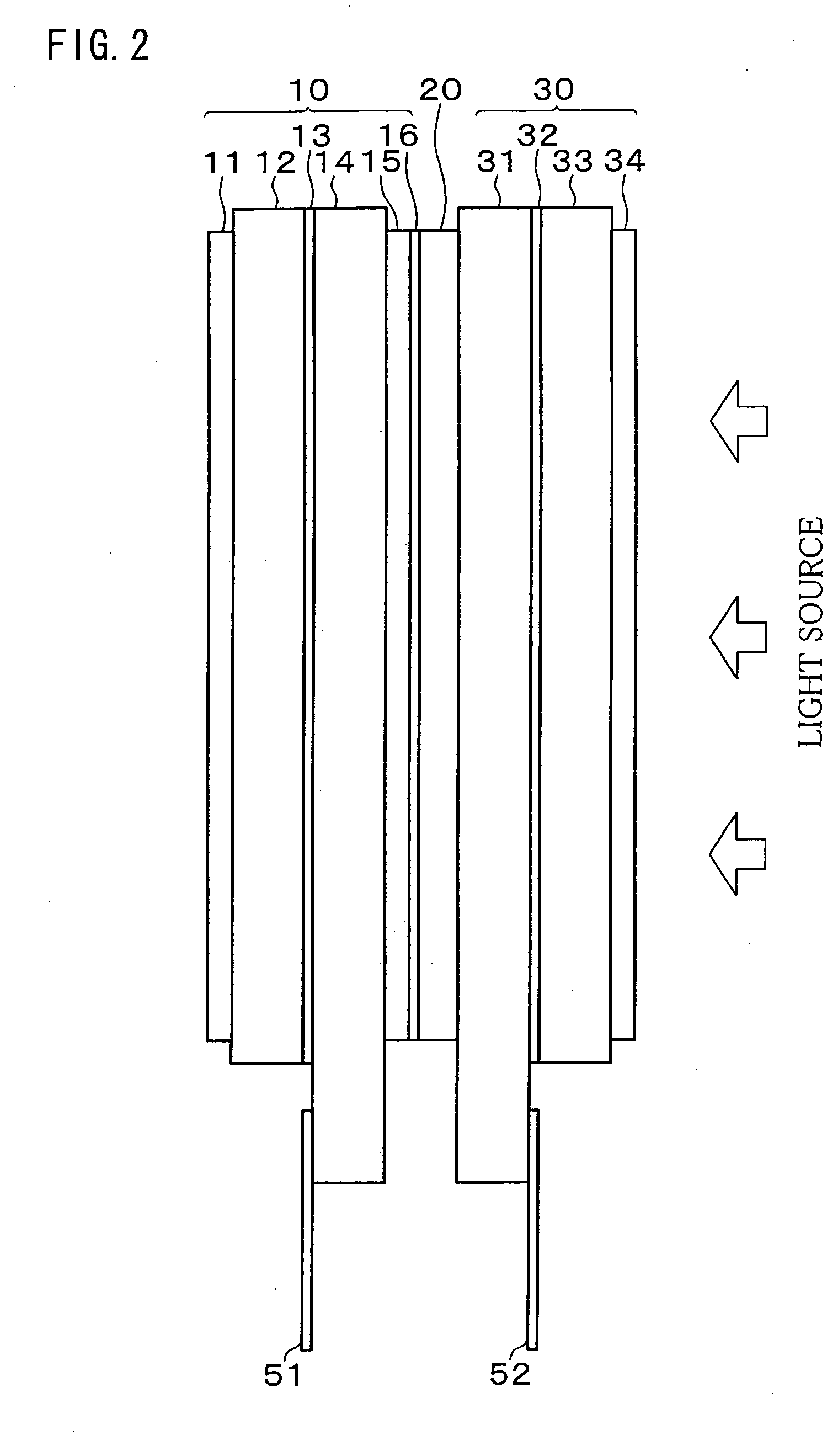
[0039] First, FIG. 2 illustrates a schematic structure of a 2D / 3D switching type liquid crystal display panel of the present embodiment. Note that, the present embodiment takes as an example a liquid crystal display panel of the present invention applied to a 2D / 3D switching type liquid crystal display panel.

[0040] As shown in FIG. 2, the 2D / 3D switching type liquid crystal display panel includes a display-use liquid crystal panel (display image generating means) 10, a patterned retardation plate (parallax barrier means) 20, and a switching liquid crystal panel 30, which are bonded together. The 2D / 3D switching type liquid crystal display panel of the present embodiment is integrated with driving circuits, a backlight (light source), and other components, which realizes a 2D / 3D switching type liquid crystal display apparatus.

[0041] The display-use liquid crystal panel 10 is provided as a ...


PUM

PropertyMeasurementUnit
widthaaaaaaaaaa
lengthaaaaaaaaaa
lengthaaaaaaaaaa

Abstract

An active matrix type display panel, used as a display-use panel, has pixel patterns each having aperture sections. The aperture sections are set to have a width satisfying the following inequality, 0<(minimum width of the aperture sections in the pixel) / (maximum width of the aperture sections in the pixel)≦0.037, or 0.130≦(minimum width of the aperture sections in the pixel) / (maximum width of the aperture sections in the pixel)<1.

Description

TECHNICAL FIELD [0001] The present invention relates to a display panel and a display apparatus which are capable of displaying different images according to a plurality of viewpoints in a similar manner to 3D (three dimensional) display. BACKGROUND ART [0002] In a normal field of vision, humans have the two eyes that perceive images which the eyes view from two different viewpoints, respectively, due to their spatial separation in the head. Parallax of the two images allows humans to recognize by the brain the images from the two different viewpoints as a stereoscopic image. By utilizing this principle, there has been developed a liquid crystal display which causes an observer to view and recognize images from two different viewpoints through the right eye and the left eye, respectively, so as to generate parallax, thereby carrying out a 3D (three-dimensional) display. [0003] In a conventional 3D liquid crystal display, images from respective different viewpoints are supplied to th...

Claims


Application Information

Patent Timeline
Patent Type & Authority Applications(United States)
IPC IPC(8): H04N13/04H04N15/00G02F1/13G02B27/22G02F1/1335G02F1/1362G09F9/30
CPCG02F1/136213H04N13/0454G02F1/136286H04N13/359
Inventor AOKI, SUNAOSAITOH, TATSUJIFUJITA, KENJIMATSUMOTO, TOSHIHIRO
Owner SHARP KK
Why Eureka
Try Eureka