Method and structure of patterning landing pad structures for spatial light modulators

a technology landing pad, which is applied in the field of manufacturing objects, can solve the problems of difficult coating on small components, inability to achieve the desired adhesion of suspended members to the electrode, and inability to manufacture so as to reduce parasitic forces and simplify fabrication. the effect of spatial light modulator components

Inactive Publication Date: 2006-12-21
MIRADIA INC
View PDF41 Cites 18 Cited by
  • Summary
  • Abstract
  • Description
  • Claims
  • Application Information

AI Technical Summary

Benefits of technology

[0013] Numerous benefits are achieved using the present invention over conventional techniques. For example, an embodiment of the present invention provides a means to simplify fabrication of spatial light modulator components. Additionally, embodiments of the present invention provide a flexible design that can be optimized to meet the needs of particular applications. For example, the size and position of landing pads may be modified depending on the design constraints presented by a given application. In addition, the flexibility of design extends to materials optimized for particular applications. In embodiments according to the present invention, complex coatings are not necessary to reduce parasitic forces present in the MEMS. In certain embodiments, the invention also provides a way of operating a MEMS device to overcome stiction forces. Depending upon the embodiment, one or more of these benefits may exist. These and other benefits have been described throughout the present specification and more particularly below.

Problems solved by technology

These parasitic forces may be strong enough to overcome the restoring force, resulting in an undesirable adhesion of the suspended member to the electrode.
Unfortunately, these techniques also have limitations.
For example, some coatings are difficult to deposit on small components and can require complex deposition equipment.
Moreover, complex mechanical structures may have reliability and lifetime concerns.
However, as with other approaches, reliability and lifetime concerns may be present in these designs.

Method used


Image

  • Method and structure of patterning landing pad structures for spatial light modulators
  • Method and structure of patterning landing pad structures for spatial light modulators
  • Method and structure of patterning landing pad structures for spatial light modulators

Examples


Embodiment Construction

[0020] According to the present invention techniques for manufacturing objects are provided. More particularly, the invention relates to a method and structure for fabricating one or more landing pads for spatial light modulators. Merely by way of example, the invention has been applied to the formation of a landing pad structure fabricated from a dielectric layer coupled to a standoff structure. The method and device can be applied to spatial light modulators as well as other devices, for example, micro-electromechanical sensors, detectors, and displays.

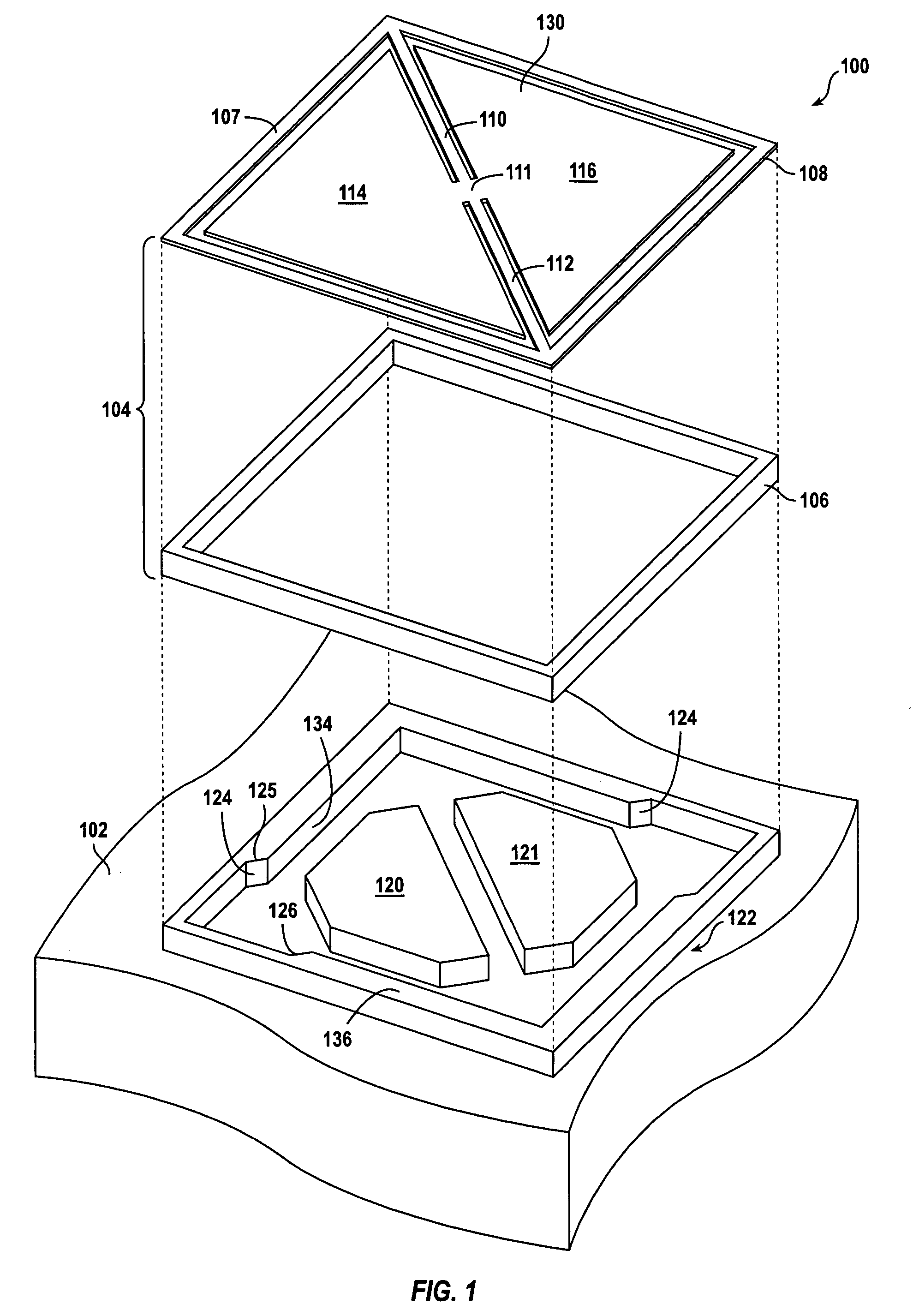
[0021]FIG. 1 is a simplified exploded perspective view of a spatial light modulator 100 according to an embodiment of the present invention. This diagram is merely an example, which should not unduly limit the scope of the claims herein. One of ordinary skill in the art would recognize many variations, modifications, and alternatives. The spatial light modulator includes an electrode substrate 102 and mirror substrate 104. For purp...


PUM


Abstract

A spatial light modulator. The spatial light modulator includes a first substrate and a standoff structure coupled to the first substrate. The spatial light modulator also includes a mirror structure coupled to the standoff structure. The mirror structure includes a mirror body comprising at least one edge region and at least one end region, a reflective layer coupled to the mirror body, and a flexible member coplanar with the mirror body. According to an embodiment of the present invention, the mirror structure rotates about the flexible member to an activated position. In the activated position, the at least one edge region of the mirror body makes contact with the standoff structure while maintaining the at least one end region free from contact with the first substrate.

Description

BACKGROUND OF THE INVENTION [0001] This present invention relates generally to manufacturing objects. More particularly, the invention relates to a method and structure for fabricating one or more landing pads for spatial light modulators. Merely by way of example, the invention has been applied to the formation of a landing pad structure fabricated from a dielectric layer coupled to a standoff structure. The method and device can be applied to spatial light modulators as well as other devices, for example, micro-electromechanical sensors, detectors, and displays. [0002] Micro-electromechanical systems (MEMS) are used in a number of application areas. For example, MEMS have been used in micro-mirror arrays, sensors, and actuators. In some of these applications, a suspended member is attracted to an electrode upon application of an electrical force and restored to an original position by a restoring force. As the suspended member approaches the electrode, surface forces can exert inf...

Claims


Application Information

Patent Timeline
Patent Type & Authority Applications(United States)
IPC IPC(8): G02B26/00
CPCG02B26/0841
Inventor YANG, XIAO
Owner MIRADIA INC
Why Eureka
Try Eureka