Light source for dental and medical procedures

a technology for dental and medical procedures and light sources, applied in the field of healthcare devices, can solve the problems of insufficient infrared energy transmission efficiency of optical fiber cables, inability to effectively transmit heat, and the fact that optical fiber cables, which are typically replaced quarterly at great expense, can last considerably longer, so as to increase the brightness of light and reduce the effect of brightness

Inactive Publication Date: 2006-12-21
SYRIBEYS PHILIP
View PDF74 Cites 12 Cited by
  • Summary
  • Abstract
  • Description
  • Claims
  • Application Information

AI Technical Summary

Benefits of technology

[0010] The light transmitted to the wand emanates from the distal end of the wand through an optical window or lens. The wand preferably includes controls for increasing and decreasing the brightness of the light emanating from the wand and may also include controls for changing the focus of the beam emanating from the wand. The LEDs used in the

Problems solved by technology

Fifth, POF does not transmit infrared energy very efficiently which prevents it from transmitting heat as much as glass fiber.
Optical fiber cables,

Method used


Image

  • Light source for dental and medical procedures
  • Light source for dental and medical procedures
  • Light source for dental and medical procedures

Examples


Embodiment Construction

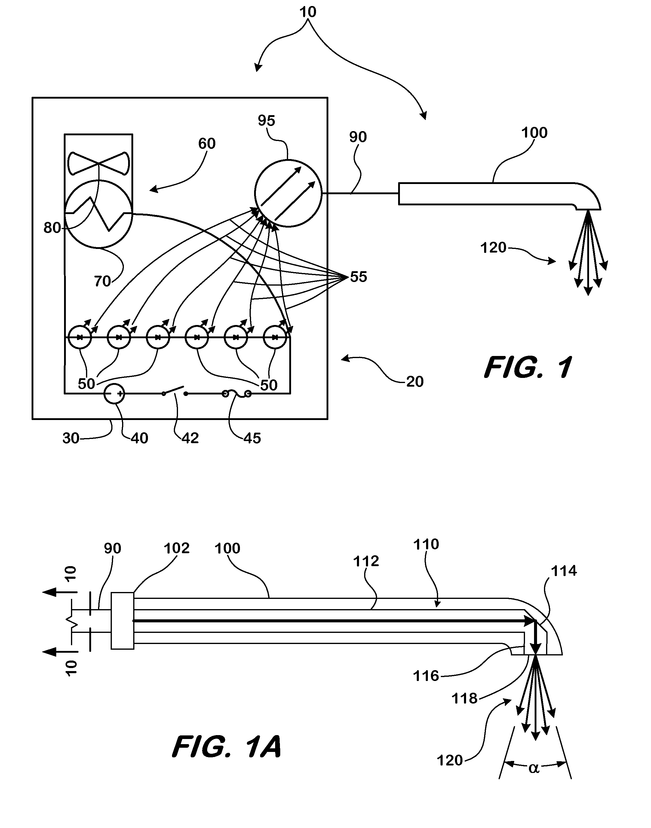
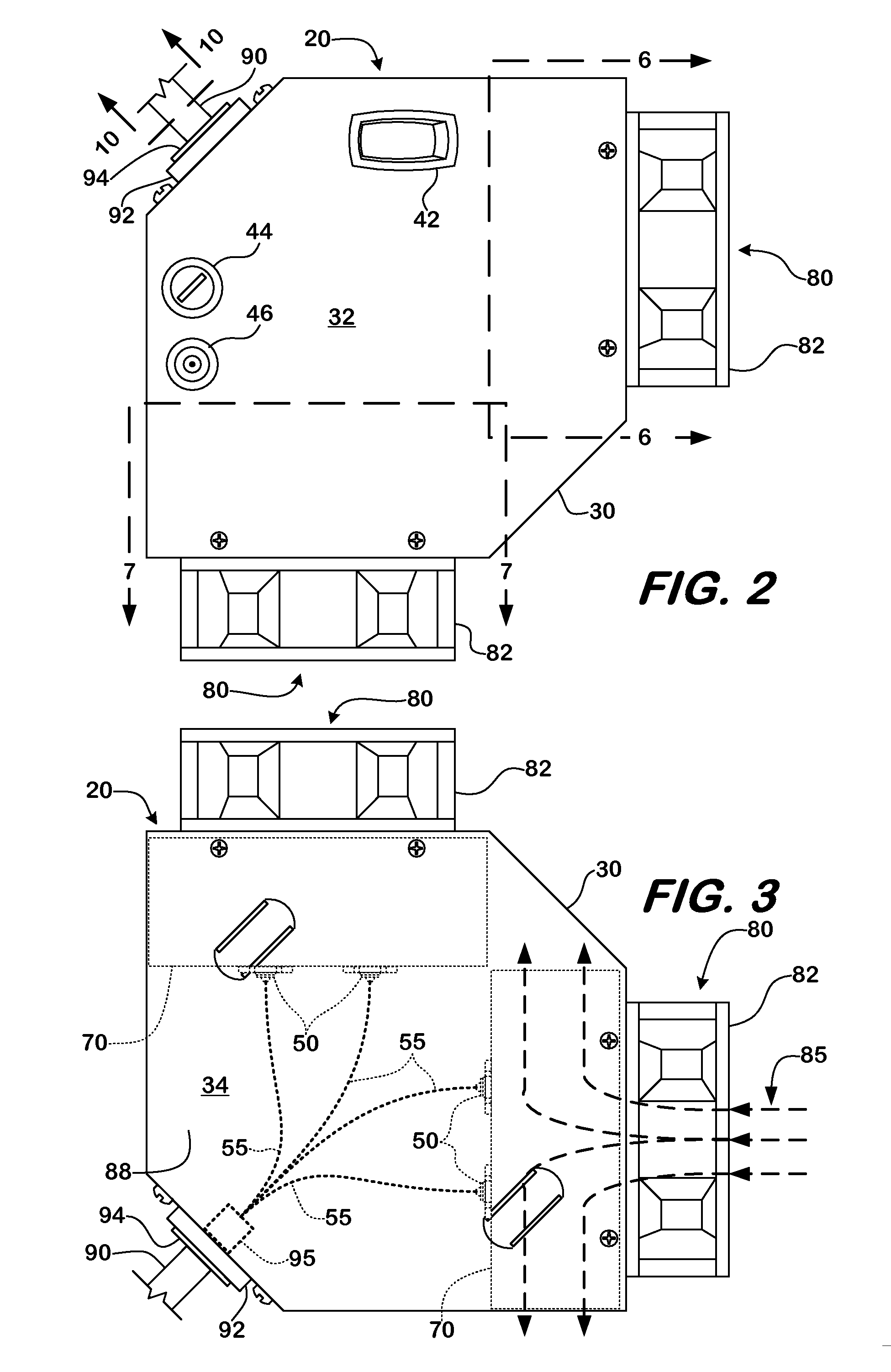
[0023] This application refers in detail below to an exemplary embodiment of a lighting system for medical procedures, which is illustrated in the accompanying drawings. Wherever possible, the application uses the same reference numbers throughout the drawings to refer to the same or similar items.

[0024] The lighting system 10 is illustrated schematically in FIG. 1 with the primary components of the system including a light source 20 having a housing 30, a power source 40, and a group of LEDs 50 with their light output individually coupled to a group of optical fibers 55. A cooling system 60 that carries heat away from the group of LEDs 50 preferably includes a heat sink 70 and a cooling fan 80. The group of optical fibers 55 guide light from the group of LEDs 50 to a light junction 95 of an optical fiber cable 90. The optical fiber cable 90 transmits the light output of the entire group of LEDs 50 to a light wand 100. Light emanates from light wand 100 in a pattern 120.

[0025] As ...


PUM


Abstract

A light source specially adapted for use in dental procedures is described. The light source includes multiple solid state sources such as LEDs. The light sources emit light of a color temperature of about 5500° K. or more, which enables a dentist using the light source to detect caries in a patient's oral cavity more easily and reliably. Each of the sources is preferably butt-coupled to one end of a single optical fiber. The sources are also thermally coupled to a cooling system, which may include fans or other active cooling elements. The sources are arranged spatially inside a housing to facilitate bundling them into a flexible optical cable. The optical cable transmits the light emitted by the sources to a conventional dental lighting handpiece.

Description

II. CROSS-REFERENCE TO RELATED APPLICATIONS [0001] This application claims the benefit of U.S. Provisional Application No. 60 / 690,560, filed Jun. 15, 2005. III. BACKGROUND OF THE INVENTION [0002] This application relates to devices used in healthcare and, more particularly, to a system for illuminating a subject for diagnostic and treatment purposes. More particularly, the application relates to a system for illuminating portions of a dental patient's oral cavity during treatment procedures. [0003] Conventional light sources used during dental procedures rely upon incandescent light sources such as halogen-based light bulbs or arc lamps such as xenon or mercury arc lamps. Light from the light source is transmitted via a fiber optic cable to a light wand or handpiece that may be inserted into a patient's oral cavity during treatment. Light exits a conventional light wand to illuminate the oral cavity during treatment. Typically, the light emanating from conventional sources has a col...

Claims


Application Information

Patent Timeline
IPC IPC(8): F21S6/00
CPCA61B5/0088F21W2131/202A61C19/004
Inventor SYRIBEYS, PHILIP J.
Owner SYRIBEYS PHILIP
Why Eureka
Try Eureka