
Zoom-type laser-assisted therapeutic instrument

A laser-assisted and therapeutic instrument technology, applied in the medical field, can solve the problems of unchangeable, fixed range, unable to focus, etc., and achieve the effects of expanding the irradiation range, reducing light diffraction, and changing the light intensity

Inactive Publication Date: 2021-09-03
黄文凯
View PDF0 Cites 0 Cited by
  • Summary
  • Abstract
  • Description
  • Claims
  • Application Information

AI Technical Summary

Problems solved by technology

[0003] Based on the inventor’s discovery above, the existing methods mainly have the following disadvantages. For example, because the therapeutic apparatus all use long-plate lighting panels, the range of irradiation is fixed, so that when the spectrum is irradiated, it will be diffracted to the surrounding crowd. And cannot focus, can only be in the state of the same irradiation intensity continuously, and cannot change the light intensity with the progress of the patient's rehabilitation

Method used


Image

  • Zoom-type laser-assisted therapeutic instrument
  • Zoom-type laser-assisted therapeutic instrument
  • Zoom-type laser-assisted therapeutic instrument

Examples


Embodiment 1

[0027] as attached figure 1 To attach Figure 7 Shown:

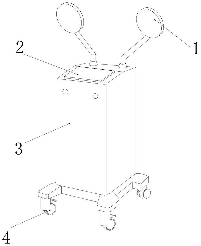
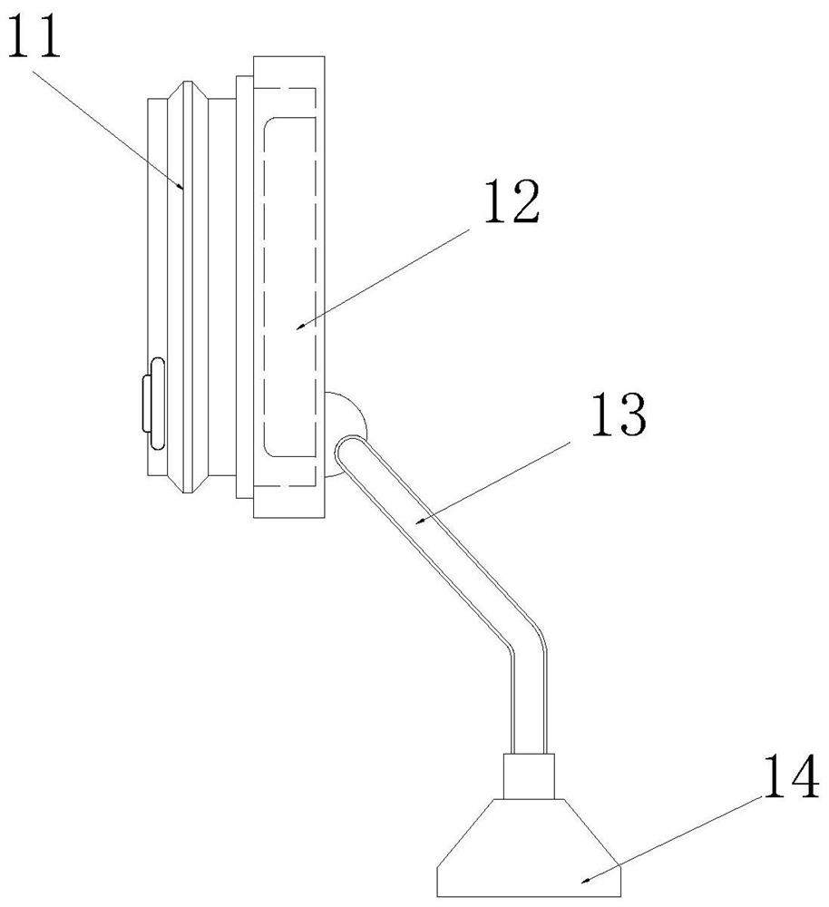
[0028] The present invention provides a zoom-type laser-assisted therapeutic apparatus, its structure includes an irradiation device 1, a control panel 2, a body 3, and a moving wheel 4. The irradiation device 1 is symmetrically installed on the upper end of the body 3, and the control panel 2 is arranged on The top of the body 3 is connected to the body 3 through wireless control. The lower end of the body 3 is rotatably arrayed with moving wheels 4; The adjusting device 11 is fixed on the left end of the lamp board 12 , the lamp board 12 is rotatably connected with a bracket 13 , and the lower end of the bracket 13 is fixed on the body 3 through a fixing seat 14 .

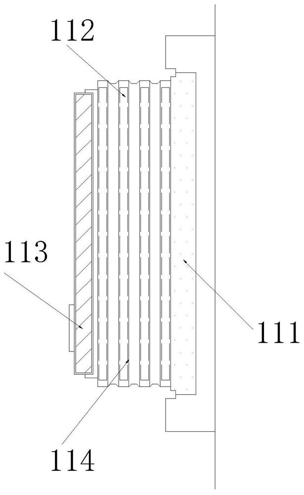
[0029] Wherein, the adjustment device 11 includes a fixed ring 111, a zoom mechanism 112, a zoom device 113, and a folding layer 114, the fixed ring 111 is adhesively fixed on the right end of the folding layer 114, and the zooming mechanism 112 is embedd...

Embodiment 2

[0038] as attached Figure 8 To attach Figure 9 Shown:

[0039]Wherein, the scaling device 113 includes a second rotating shaft 131, a pushing device 132, a wire 133, a cavity 134, and a swing blade 135, and the second rotating shaft 131 is fixed on the end of the swing blade 135, and the pushing device 132 passes through a wire 133 Controlled connection with the controller 136, the wires 133 and each of the pushing devices 132 are connected in series one by one, the cavity 134 is rotatably fixed in the scaling device 113 through the second rotating shaft 131, and the swinging In the blade 135 and the scaling device 113, the controller 136 is electrically connected to the pushing device 132 by a wire 133, and the second rotating shaft 131, the pushing device 132, and the swinging blade 135 are all provided with three groups, and the swinging blade 135 can be moved when gathering. Cover the swing vane 135 .

[0040] Wherein, the pushing device 132 includes a magnetic block ...


PUM


Abstract

The invention discloses a zoom-type laser-assisted therapeutic instrument which structurally comprises irradiation devices, a control panel, a machine body and moving wheels, the irradiation devices are symmetrically installed at the upper end of the machine body, the control panel is arranged above the machine body and connected with the machine body through wireless control, the moving wheels are rotatably arrayed at the lower end of the machine body, each of the irradiation devices comprises an adjusting device, a lamp panel, a support and a fixing base, the adjusting device is fixed to the left end of the lamp panel, the lamp panel is rotatably connected with the support, the lower end of the support is fixed to the machine body through the fixing base, a closing strip is fixed to the right end of a convex mirror in an adhesive mode and is in a rectangular shape, when the convex mirror is embedded in a folding layer, the protruding part of the closing strip can cover the gap on the folding layer, diffraction of light irradiation of the device is reduced, the focusing state of the device can be effectively changed through the design, and therefore the illumination intensity is changed.

Description

technical field [0001] The invention belongs to the medical field, and more specifically relates to a zoom-type laser-assisted therapeutic apparatus. Background technique [0002] The laser-assisted therapy instrument is a kind of spectrum irradiating the surface of the human body or the surface of the cavity by irradiating the spectrum of the specified band temperature through the photothermal equipment. Through the photothermal compound effect, it can effectively kill the diseased cells and tissues, coagulate the mucosal tissue, and occlude the blood vessels. To achieve the purpose of healing, the product names often used in practical applications include: visible light therapy device, light therapy device, light radiation therapy device, photon therapy device, red light therapy device, blue light therapy device, etc. [0003] Based on the inventor’s discovery above, the existing methods mainly have the following deficiencies. For example, because the therapeutic apparatus...

Claims


Application Information

Patent Timeline
Patent Type & Authority Applications(China)
IPC IPC(8): A61N5/067A61N5/06
CPCA61N5/0613A61N2005/0632A61N2005/0658A61N2005/0664
Inventor 黄文凯
Owner 黄文凯
Learn More