

Method of growing piezoelectric lanthanide gallium crystals
a technology of piezoelectric lanthanide gallium and crystal growth method, which is applied in the direction of single crystal growth, polycrystalline material growth, eutectic material solidification, etc., can solve the problems of scattering and/or cracking, the piezoelectric behavior of different wafers can vary by up to 30%, and the cost of the product increases by up to 30%. , to achieve the effect of improving temperature stability, reducing power flow angle and reducing diffraction
- Summary
- Abstract
- Description
- Claims
- Application Information
AI Technical Summary
Benefits of technology
Problems solved by technology
Method used
Image

Examples
embodiment 1
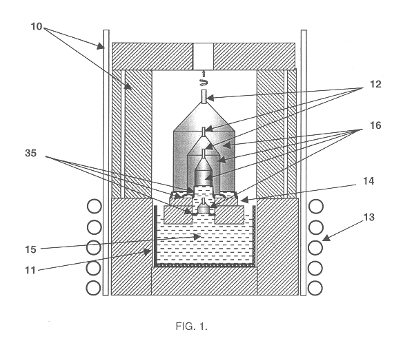
A single crystal of La.sub.3 Ga.sub.5.5 Nb.sub.0.5 O.sub.14, was grown by a drawing seed crystal 12 from a melt 15 through a dipped forming mould 14 as shown in FIG. 1.
The starting materials were prepared by drying and mixing 99.999% pure La.sub.2 O.sub.3, Ga.sub.2 O.sub.3, and Nb.sub.2 O.sub.5 powders in a stoichiometric ratio, pressing, and then melting in several steps in a cylindrical iridium crucible 11 of 150 mm diameter and 150 mm height with a wall thickness 2.0 mm. Mounted in the thermal unit 10 of the CRYSTAL-3M growth machine, the iridium crucible 11 containing a 120-mm diameter forming mould was heated by a conventional RF heating method. Growth was performed in an atmosphere of mixed argon and oxygen the oxygen content of which was 1.5 vol %. The revolving seed crystal 12 oriented at 54 deg to the "Y" axis was brought in contact with the surface of melt 15 at a frequency of rotation of 3-18 1 / minute. The crystal growth process continued until the solidified fraction g w...
embodiment 2
A single crystal of La.sub.3 Ga.sub.5 SiO.sub.14, was grown by drawing a seed crystal 12 from a melt 15 through a dipped forming mould 14 as shown in FIG. 1.
The starting materials were prepared by drying, mixing 99.999% pure La.sub.2 O.sub.3, Ga.sub.2 O.sub.3, and SiO.sub.2 powders in a stoichiometric ratio, pressing, and then melting these powders in several steps in a cylindrical iridium crucible 11 having 120 mm in diameter and 120 mm in height with a wall thickness 2.0 mm. Mounted in the thermal unit 10 of the CRYSTAL-3M growth machine the iridium crucible 11 containing a 90-mm diameter forming mould was heated by a conventional RF heating method. Growth was performed in an argon atmosphere. The revolving seed crystal 12 oriented at 54 deg to the "Y" axis was brought in contact with the surface of the melt 15 at a frequency of rotation of 3-18 1 / minute. The crystal growth process was continued until the solidified fraction g was approximately 0.7. The pulling rate was 0.7 mm / hou...
embodiment 3
A single crystal of La.sub.3 Ga.sub.5.5 Ta.sub.0.5 O.sub.14, was grown by drawing a seed crystal 12 from a melt 15 through a dipped forming mould 14 as shown in FIG. 3.
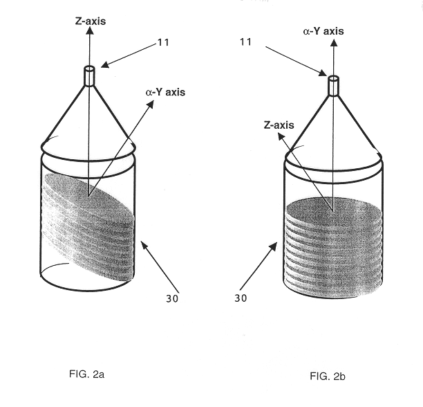
The starting materials were prepared by drying and mixing 99.999% pure La.sub.2 O.sub.3, Ga.sub.2 O.sub.3, and Ta.sub.2 O.sub.5 powders in a stoichiometric ratio, pressing, and then melting these powders in several steps in a cylindrical iridium crucible 11 having 120 mm diameter and 120 mm height with a wall thickness 2.0 mm. Mounted in the thermal unit 10 of the CRYSTAL-3M growth machine the iridium crucible 11 containing a 88-mm.times.88-mm forming mould was heated by a conventional RF heating method. Growth was performed in a mixture of nitrogen and oxygen (the content of oxygen is up to 20 vol %). The revolving seed crystal 12 oriented along the crystallographic Z-axis was brought in contact with the surface of the melt 15 at frequency of rotation of 1-7 1 / minute. The crystal growth process was continued until th...
PUM
| Property | Measurement | Unit |
|---|---|---|
| angle | aaaaa | aaaaa |
| diameter | aaaaa | aaaaa |
| thickness | aaaaa | aaaaa |
Abstract
Description
Claims
Application Information