Acoustic wave resonator

a technology of acoustic waves and resonators, applied in piezoelectric/electrostrictive/magnetostrictive devices, piezoelectric/electrostriction/magnetostriction machines, electrical apparatus, etc., can solve the problem of purious responses caused by transverse modes, concentration of power consumption at the center of the idt electrode, etc. problem, to achieve the effect of satisfying the resonance characteristics

Active Publication Date: 2008-12-18
MURATA MFG CO LTD
View PDF16 Cites 19 Cited by
  • Summary
  • Abstract
  • Description
  • Claims
  • Application Information

AI Technical Summary

Benefits of technology

[0011]To overcome the problems described above, preferred embodiments of the present invention provide a surface acoustic wave resonator which utilizes acoustic waves other than leaky acoustic waves, such as Love waves and Rayleigh waves, and is not vulnerable to the effects of spurious responses caused by a transverse mode and that is capable of increasing Q at an anti-resonant frequency and providing satisfactory resonance characteristics.

Problems solved by technology

The surface acoustic wave resonator 501 utilizes resonance characteristics based on Love waves, and there is a problem in that spurious responses caused by transverse modes are generated.
However, there is a problem with the apodization weighting described in Japanese Patent No. 2645674 in that the center portion of the IDT electrode 512 has a very large cross width.
That is, the IDT electrode 512 has a large maximum cross width, and thus, has long electrode fingers, which results in a concentration of power consumption at the center of the IDT electrode 513.
This decrease the power resistance.
Furthermore, the surface acoustic wave resonator 511 has another problem in that the Q factor at an anti-resonant frequency is not sufficiently high.
Love waves and Rayleigh waves have relatively low acoustic velocities and are likely to be confined in an IDT, which may result in the generation of a transverse mode.
When using acoustic waves, such as Love waves and Rayleigh waves, which have relatively low acoustic velocities and are not leaky waves, it is difficult to suppress a transverse mode causing spurious responses by adjusting the crystal orientation of a piezoelectric substrate.

Method used


Image

  • Acoustic wave resonator
  • Acoustic wave resonator
  • Acoustic wave resonator

Examples


Embodiment Construction

[0043]Preferred embodiments of the present invention will be described in detail with reference to the drawings.

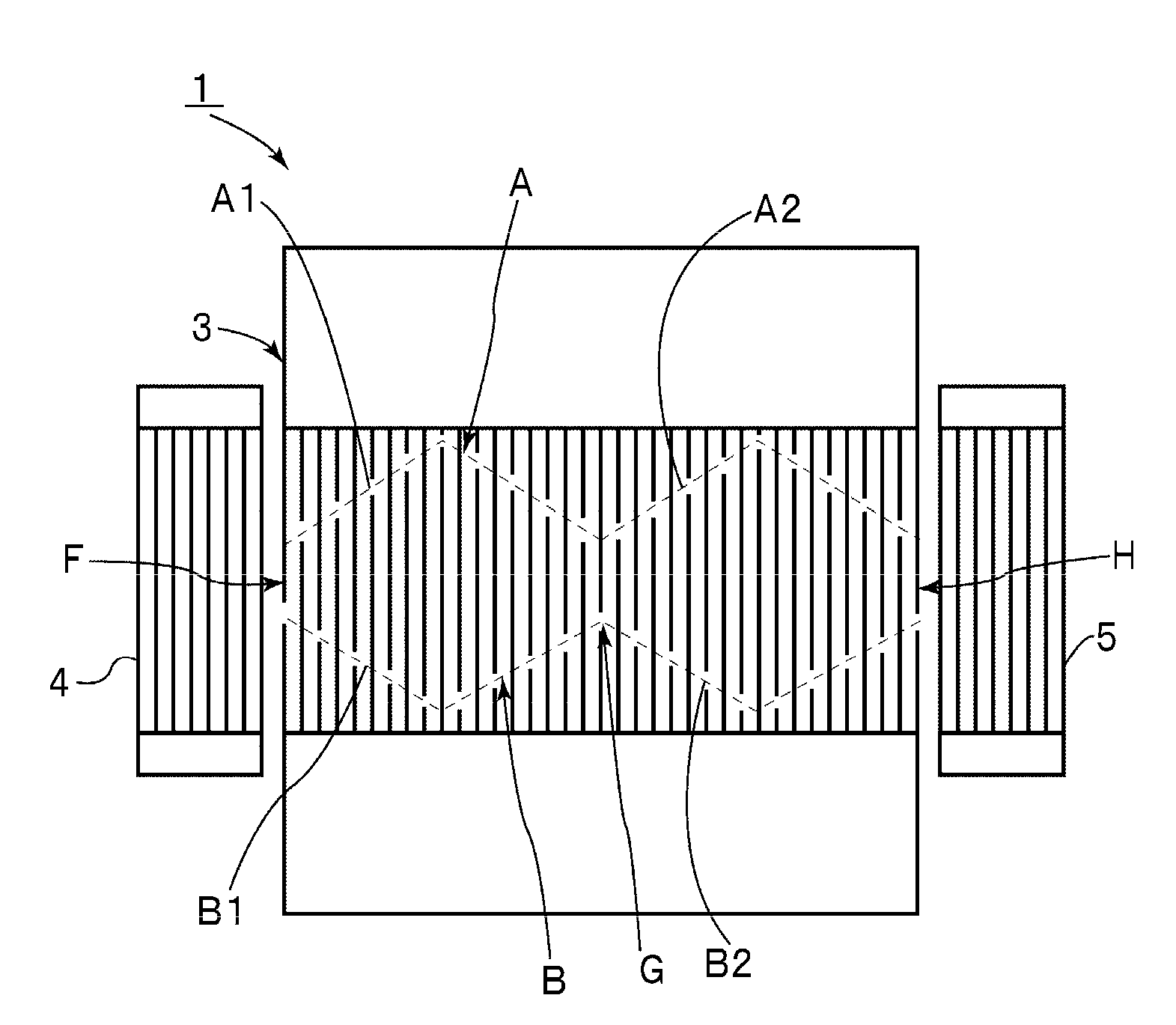
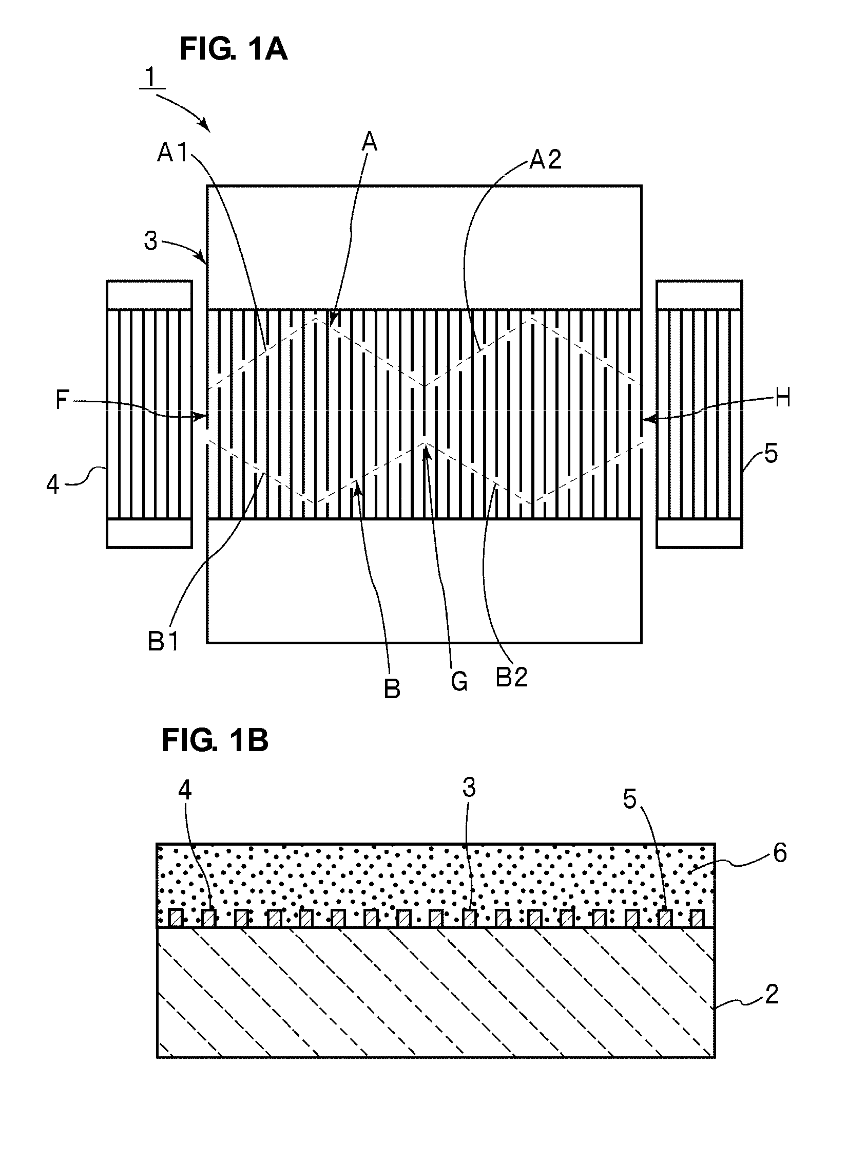
[0044]FIG. 1A is a schematic plan view illustrating an electrode structure of a surface acoustic wave resonator according to a first preferred embodiment of the present invention and FIG. 1B is a schematic elevational cross-sectional view of the surface acoustic wave resonator shown in FIG. 1A. A surface acoustic wave resonator 1 includes a piezoelectric substrate 2. In the present preferred embodiment of the present invention, the piezoelectric substrate 2 is preferably made of a 126-degree Y-cut, X-propagating LiNbO3 substrate, for example. Note that the piezoelectric substrate 2 may be made of a LiNbO3 substrate having another crystal orientation or of another piezoelectric single crystal such as LiTaO3. In addition, the piezoelectric substrate 2 may be made of piezoelectric ceramics. Further, the piezoelectric substrate 2 may have a structure in which a piezoelectric f...


PUM


Abstract

In an acoustic wave resonator, an IDT electrode is provided on a piezoelectric substrate. The IDT electrode is apodization-weighted such that a plurality of maximum values of cross widths are provided in acoustic wave propagation directions. Alternatively, in apodization weighting, weighting is applied such that at least one of a pair of envelopes located at outer side portions of the IDT electrode in directions substantially perpendicular to acoustic wave propagation directions includes a plurality of angled envelope portions angled from a central portion of the IDT electrode toward an outer side portion of the IDT electrode in a direction substantially perpendicular to the acoustic wave propagation directions.

Description

BACKGROUND OF THE INVENTION[0001]1. Field of the Invention[0002]The present invention relates to acoustic wave resonators utilizing surface acoustic waves or boundary acoustic waves. More particularly, the present invention relates to a one-port acoustic wave resonator in which apodization weighting is applied to IDT electrodes.[0003]2. Description of the Related Art[0004]Various resonators utilizing surface acoustic waves and boundary acoustic waves have been disclosed in the past. For example, Japanese Patent No. 2645674 indicated below discloses a surface acoustic wave resonator illustrated in FIG. 16 and FIG. 17. A surface acoustic wave resonator 501 illustrated in FIG. 16 is a surface acoustic wave resonator utilizing Love waves described in Japanese Patent No. 2645674 as an example of the related art. In this surface acoustic wave resonator 501, an interdigital transducer (IDT) electrode 503 is provided on a piezoelectric substrate 502. The IDT electrode 503 is a normal IDT el...

Claims


Application Information

Patent Timeline
Patent Type & Authority Applications(United States)
IPC IPC(8): H03H9/25H03H9/15
CPCH03H9/02818H03H9/02992H03H9/1452
Inventor NAKAO, TAKESHINAKAI, YASUHARUKADOTA, MICHIO
Owner MURATA MFG CO LTD
Why Eureka
Try Eureka