Lighting device for vehicle

a technology for lighting devices and vehicles, applied in vehicle interior lighting, transportation and packaging, lighting and heating equipment, etc., can solve the problems of inability to provide lighting devices, large width in forward and backward direction of lighting devices, etc., to achieve easy formation of desired light distribution patterns, improve accuracy, and increase the degree of freedom in layou

Inactive Publication Date: 2006-12-21
KOITO MFG CO LTD
View PDF3 Cites 55 Cited by
  • Summary
  • Abstract
  • Description
  • Claims
  • Application Information

AI Technical Summary

Benefits of technology

[0027] Instead of this configuration, a bright spot-shaped light distribution pattern may be formed, as the first reflection surface is formed of a curved surface formed by rotating the ellipse forming the cross-sectional shape of the predetermined plane around the optical axis, and the second reflection surface is formed of a curved surface formed by rotating the parabola forming the cross-sectional shape of the predetermined plane around the optical axis. Moreover, by using this configuration, the second reflection surface can be formed in a circular ring shape, when seen from the front view of the lighting device. Accordingly, the light distribution pattern has balanced luminous intensity distribution along the entire periphery of the pattern.
[0028] In the above-described configuration, the first and second reflection surfaces may be separately formed on the surface of each reflector. However, if the first and second reflection surfaces are formed on the surface of a single translucent block, the lighting device can be made thin, and the positional relationship between the first reflection surface and the second reflection surface can improve accuracy.
[0029] When this configuration is used, since the translucent block outputs the light reflected by the second reflection surface, it is possible to control diffusion and deviation of the light output from the translucent block, by properly forming the surface shape of the output surface. Therefore, it is possible to easily form the desired light distribution pattern.
[0030] Moreover, since the light reflected by the second reflection surface arrives at the output surface of the translucent block in a parallel pattern, even though the position of the output surface is deviated in the forward and backward direction, the translucent block outputs the light without changing the direction of the light. Therefore, it is possible to properly adjust the position of the output surface of the translucent block in accordance with the shape of the space for mounting the lighting device in the vehicle. Accordingly, it is possible to increase the degree of freedom in the layout of the lighting device.

Problems solved by technology

Consequently, the width in the forward and backward direction of the lighting device becomes large.
For this reason, there is a problem in which a lighting device cannot be provided when a space for mounting the lighting device in the vehicle does not provide sufficient width in the forward and backward direction.

Method used


Image

  • Lighting device for vehicle
  • Lighting device for vehicle
  • Lighting device for vehicle

Examples


first embodiment

[0049] Hereinafter, embodiments of the invention will be described with reference to the accompanying drawings. First, the invention will be described.

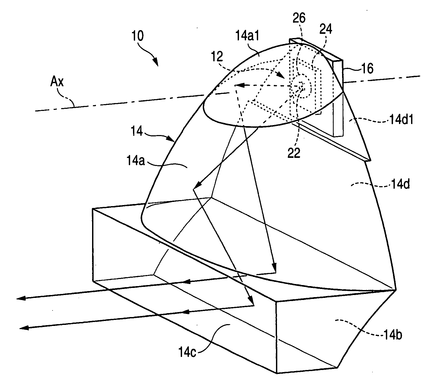
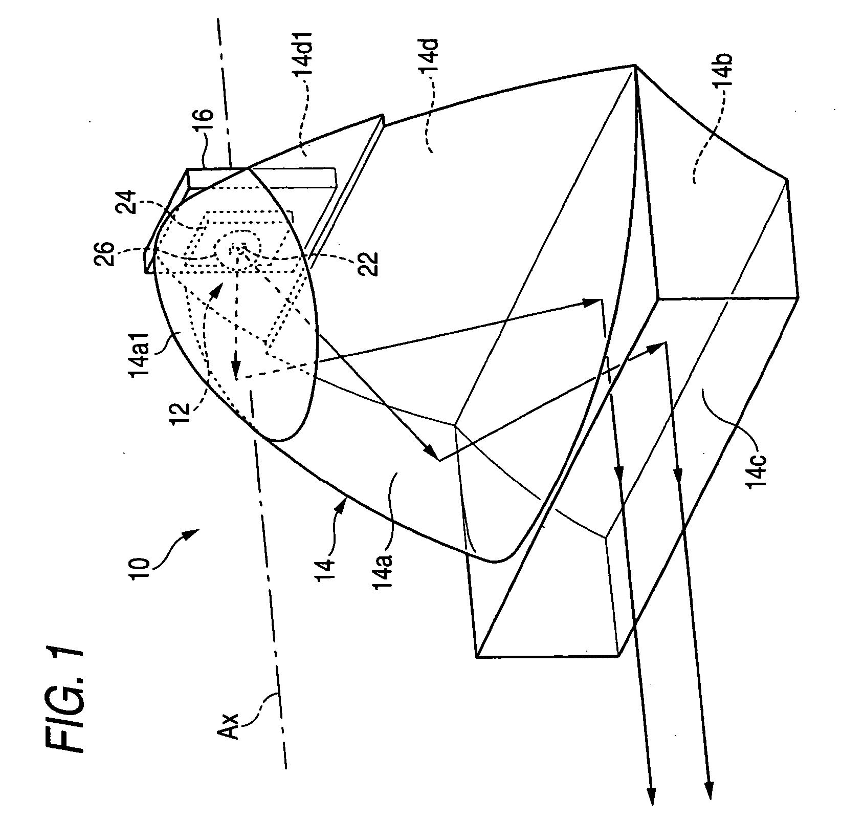
[0050]FIG. 1 is a perspective view of a lighting device for a vehicle 10 according to a first embodiment of the invention,

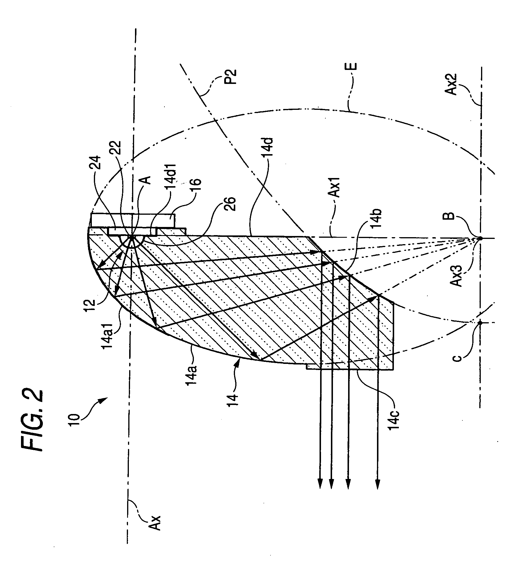
[0051]FIG. 2 is a cross-sectional side view thereof, and FIG. 3 is a front view thereof.

[0052] As shown in the FIG. 1 to 3, the lighting device for a vehicle 10 is a lighting device unit that is used in a state built in a headlamp for high beam, and includes a light-emitting element 12 and a translucent block 14 made of transparent resin materials. The light-emitting element 12 is disposed in a forward direction of the lighting device on an optical axis Ax extending in the forward and backward direction of the lighting device. The translucent block 14 covers the forward side of the light-emitting element 12. While the lighting device 10 is built in the headlamp, its optical axis Ax extends in a forward and backwa...

second embodiment

[0127] Hereinafter, a second embodiment according to the invention will be described.

[0128]FIG. 15 is a front view showing a lighting device 710 according to a second embodiment of the invention.

[0129] As shown in FIG. 15, the lighting device 710 for a vehicle has the same configuration as the lighting device 10 for a vehicle according to the first embodiment in its fundamental structure. However, the lighting device 710 for a vehicle has differences from the first embodiment in the surface shape of a first reflection surface 714a and a second reflection surface 714b of a translucent block 714 and an external shape of an output surface 714c.

[0130] That is, the first reflection surface 714a is formed of a rotary elliptic surface in which the major axis Ax1 of the ellipse E forming the cross-sectional shape taken along the predetermined plane of the first reflection surface 14a according to the first embodiment is set to be a central axis. In addition, the second reflection surface ...

third embodiment

[0138] Hereinafter, a third embodiment according to the invention will be described.

[0139]FIG. 17 is a cross-sectional plan view showing a lighting device 810 for a vehicle according to the third embodiment of the invention.

[0140] As shown in FIG. 17, a translucent block 814 of the lighting device 810 for a vehicle has the same horizontal cross-sectional shape as that of the translucent block 614 of the lighting device 610 for a vehicle according to the sixth modification of the first embodiment, and has a rotary body formed as the horizontal cross-sectional shape is rotated around the optical axis Ax.

[0141] That is, a first reflection surface 814a of the translucent block 814 is formed of a curved surface formed as the ellipse E forming the cross-sectional shape of the predetermined plane is rotated around the optical axis Ax. A second reflection surface 814b is formed of a curved surface formed as the parabola P2 forming the cross-sectional shape of the predetermined surface is ...


PUM


Abstract

A first reflection surface reflects light from the light-emitting element disposed on an optical axis Ax extending in the forward and backward direction of the lighting device downward, and the light is reflected in the forward direction by the second reflection surface. A cross-sectional shape taken along a vertical surface including the optical axis Ax is an ellipse E having a light-emitting center A of the light-emitting element as a first focus, and an axis line Ax1 orthogonal to the optical axis Ax as a major axis. In addition, the second reflection surface is disposed between the first focus A and the second focus B of the ellipse E. A cross-sectional shape of the second reflection surface taken along the predetermined plane is the parabola P2 having the second focus B as its focus, and the point C located ahead of the focus B as its fixed point. In this way, as the light reflected by the first reflection surface 14a is incident on the second reflection surface 14b before being converged at the second focus B, the lighting device can be made thin.

Description

BACKGROUND OF THE INVENTION [0001] 1. Technical Field [0002] The present invention relates to a lighting device for a vehicle using a light-emitting element, such as a light-emitting diode, as a light source. [0003] 2. Related Art [0004] Recently, a lighting device has been developed for a vehicle, such as a headlamp, using a light-emitting element, such as an LED, as a light source. [0005] Disclosed in Patent Document 1 is a lighting device for a vehicle including a first reflection surface which reflects light from a light-emitting element disposed toward the lateral side of the lighting device toward the rear side of the lighting device, and a second reflection surface which reflects the light reflected from the first reflection surface toward the front side of the lighting device. In the lighting device disclosed in Patent Document 1, the first reflection surface is a rotary elliptic surface having the light-emitting center of the light-emitting element as a first focus and a po...

Claims


Application Information

Patent Timeline
Patent Type & Authority Applications(United States)
IPC IPC(8): F21V7/00
CPCF21S48/1159F21S48/1329F21V7/08F21V7/06F21S48/1388F21S41/143F21S41/147F21S41/285F21S41/321F21S41/322F21S41/37F21S41/365F21S41/36
Inventor OKADA, NORIKO
Owner KOITO MFG CO LTD
Why Eureka
Try Eureka