Hologram device and hologram recording/reproducing method

Inactive Publication Date: 2006-12-21
SONY CORP
View PDF8 Cites 5 Cited by
  • Summary
  • Abstract
  • Description
  • Claims
  • Application Information

AI Technical Summary

Benefits of technology

[0011] It is desirable to provide a hologram recording / reproducing method which prevents discarding of a whole medium as a result of a writing error, and which achieves smooth and fast additional writing by having only a single schedule for additional writing. In addition, it is also desirable to provide a hologram device which uses this method.
[0016] Accordingly, in a hologram recording / reproducing operation based on an angular multiplexing technique, multiplex recording of information on a book may be performed, for example, in a period in which an angle of a mirror for changing an incident angle between a normal vector of a hologram recording medium and an incidence vector of reference light is increased, whereas a reproducing operation for reading out the information from the book may be performed in a period in which the angle is decreased. The multiplex recording operation and the reproducing operation are performed in an alternating fashion. In addition, an error inspection of the reproduction information may be implemented, and if an error is inspected, the corresponding original recorded information may be recorded onto a new book. Consequently, this prevents the whole medium from being discarded as a result of a writing error. Furthermore, since the recording may be performed in a period in which the angle of the mirror, for example, is increased, only a single schedule for changing the intensity ratio between the signal light and the reference light by means of the incident angle of the reference light may be necessary. Thus, when performing additional writing, a recording operation can be implemented simply in accordance with this schedule, thereby achieving a smooth and fast additional writing operation.

Problems solved by technology

However, it may actually be difficult to attain this movement characteristic since the zero-returning sections are overhead.
This complicates the control operation and may take too much time for the schedule selection for additional writing, thus resulting in a bad startup.

Method used


Image

  • Hologram device and hologram recording/reproducing method
  • Hologram device and hologram recording/reproducing method
  • Hologram device and hologram recording/reproducing method

Examples


first embodiment

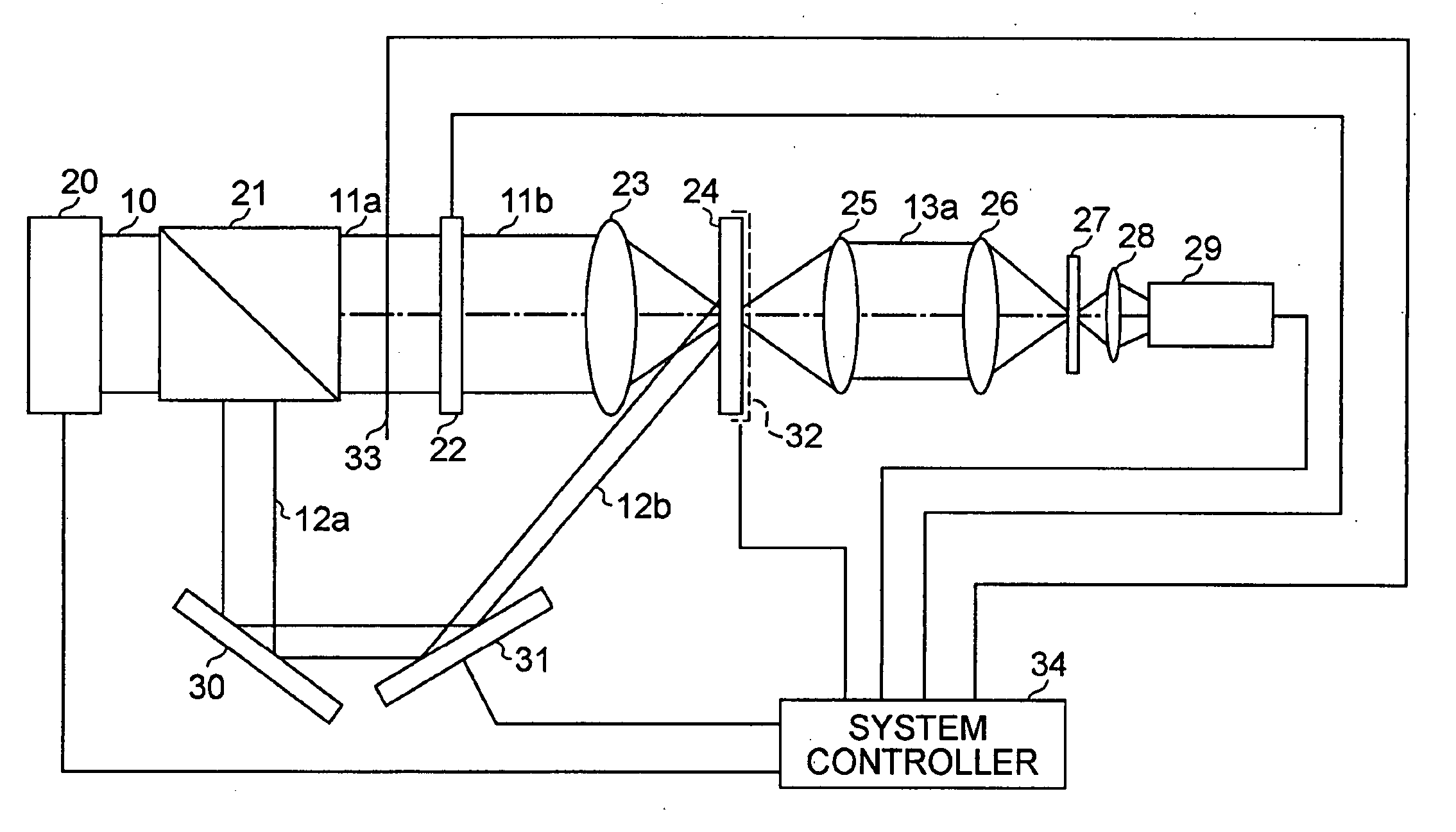
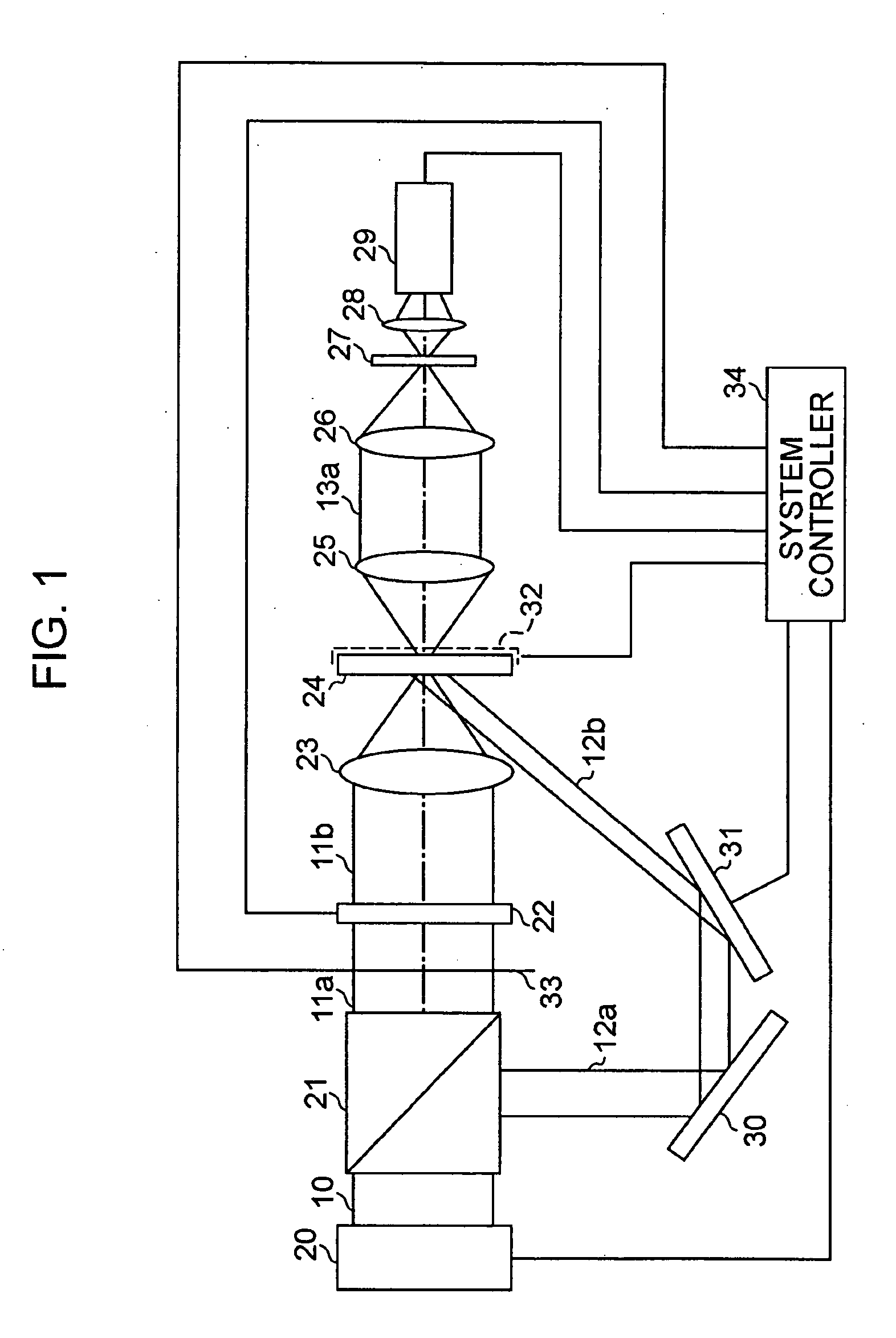
[0022]FIG. 1 is a block diagram of a hologram device according to a first embodiment of the present invention. The hologram device includes a laser light source 20, a polarizing beam splitter (PBS) 21, a spatial modulator 22, a signal-light lens 23, a hologram recording medium 24, reproduction-light lenses 25 and 26, a diaphragm 27, a lens 28, an image-capturing unit 29, a path-changing mirror 30, an angle-adjustable mirror 31, a stage 32 for moving the hologram recording medium 24, a shutter 33 that transmits or intercepts signal light, and a system controller 34 that controls the operation of the device.

[0023] The operation of the hologram device according to the first embodiment will be described below. When performing a recording operation, the system controller 34 opens the shutter 33. The laser light source 20 emits a laser beam 10, which is split into a P-wave 11a and an S-wave 12a by the PBS 21. The laser light source 20 is generally a type that generates light on a wavelen...


PUM


Abstract

In a hologram device which records information of an interference fringe of signal light and reference light onto a hologram recording medium and which reproduces the recorded information by emitting the reference light onto a recording area of the hologram recording medium, the device includes a recording / reproducing controller performing a control operation of repeatedly recording the information and reproducing the recorded information immediately after the recording of the information in an alternating fashion.

Description

CROSS REFERENCES TO RELATED APPLICATIONS [0001] The present invention contains subject matter related to Japanese Patent Application JP 2005-168179 filed in the Japanese Patent Office on Jun. 8, 2005, the entire contents of which are incorporated herein by reference. BACKGROUND OF THE INVENTION [0002] 1. Field of the Invention [0003] The present invention relates to a hologram recording / reproducing method for recording an interference fringe of two light beams onto a hologram recording medium and for reproducing data on the basis of light diffracted by the recorded interference fringe, and to a hologram device. [0004] 2. Description of the Related Art [0005] In recent years, holographic technology has been developed rapidly towards practical application of a holographic memory, which is drawing much attention as a powerful candidate against optical discs of the next generation and the generation after that. Development of a holographic data storage system that performs recording and...

Claims


Application Information

Patent Timeline
IPC IPC(8): G11B7/00
CPCG11B7/0065G11B7/08564G11B7/00772
Inventor HAYASHI, KUNIHIKOKIHARA, NOBUHIROMAEDA, MUNEYASU
Owner SONY CORP
Why Eureka
Try Eureka