Infrared signature capture device

a capture device and infrared technology, applied in computing, instruments, electric digital data processing, etc., can solve the problems of resistive screen scratching and cloudy, difficult to read instructions and/or signature templates that are often laid under resistive screen, and customers often do not realiz

Inactive Publication Date: 2006-12-21
IBM CORP
View PDF9 Cites 7 Cited by
  • Summary
  • Abstract
  • Description
  • Claims
  • Application Information

AI Technical Summary

Benefits of technology

[0005] The present invention recognizes the need for a written signature reading device. Thus, the present system discloses an infrared detection system that detects movement of a stylus pen about a signature pad. A tip of the stylus pen includes a low-power infrared signal broadcaster. The low-power infrared signal is detected by infrared sensors

Problems solved by technology

A major drawback to such systems, however, is that customers often do not realize that a non-marring stylus pen is to be used, and instead use their personal ink pens against the resistive screen.
While the resistive screen will usually still record t

Method used


Image

  • Infrared signature capture device
  • Infrared signature capture device
  • Infrared signature capture device

Examples


Embodiment Construction

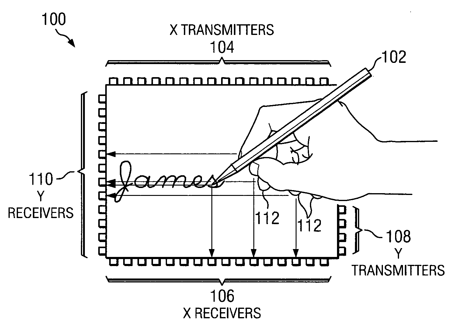
[0019] With reference now to the figures, and in particular to FIG. 1, there is depicted an exemplary signature pad 100 that uses a signal blocking stylus pen 102 (which is inert—having no special features other than the ability to block an infrared signal), an array of X-axis infrared transmitters 104 with a corresponding array of X-axis infrared receivers 106, and an array of Y-axis infrared transmitters 108 with their corresponding array of Y-axis infrared receivers 110. As signal blocking stylus pen 102 moves about signature pad 100, signal blocking stylus pen 102 blocks the infrared signals between the infrared transmitters and receivers to create a log of the signal blocking stylus pen 102's movement.

[0020] A problem with signature pad 100 is that anything that can block the infrared signals being transmitted can result in a false indicator of stylus movement. For example, a user's fingers 112 lying on signature pad 100 may cause a false blockage signal. To minimize the poten...


PUM


Abstract

A method and system for capturing a written signature is presented. A tip of an infrared transmitting pen transmits an infrared signal to infrared sensors that are aligned along two sides of a rectangular writing surface. As a person's signature is written with the infrared transmitting pen, the sensors capture the written signature.

Description

BACKGROUND OF THE INVENTION [0001] 1. Technical Field [0002] The present invention relates in general to the field of computers, and in particular to computers used to capture hand written signatures. Still more particularly, the present invention relates to an infrared emitting pen whose movements are captured by sensors that are peripheral to a writing surface. [0003] 2. Description of the Related Art [0004] At many check-out stations in grocery stores and other retail establishments, customers now sign their name, to authorize a charge or to accept a debit to their account, on a resistive screen. The resistive screen detects pressure from a stylus pen, and translates the movement of the stylus pen into a graphic file that reflects the customer's written signature. A major drawback to such systems, however, is that customers often do not realize that a non-marring stylus pen is to be used, and instead use their personal ink pens against the resistive screen. While the resistive sc...

Claims


Application Information

Patent Timeline
IPC IPC(8): G06K9/00G09G5/00
CPCG06K9/222G06V30/1423
Inventor LANDERS, JOHN DAVID JR.STEINER, DAVID JOHNWOOD, KIMBERLY ANN
Owner IBM CORP
Why Eureka
Try Eureka