

Fiber-optic premises wiring system
- Summary
- Abstract
- Description
- Claims
- Application Information
AI Technical Summary
Benefits of technology
Problems solved by technology
Method used
Image

Examples
Embodiment Construction
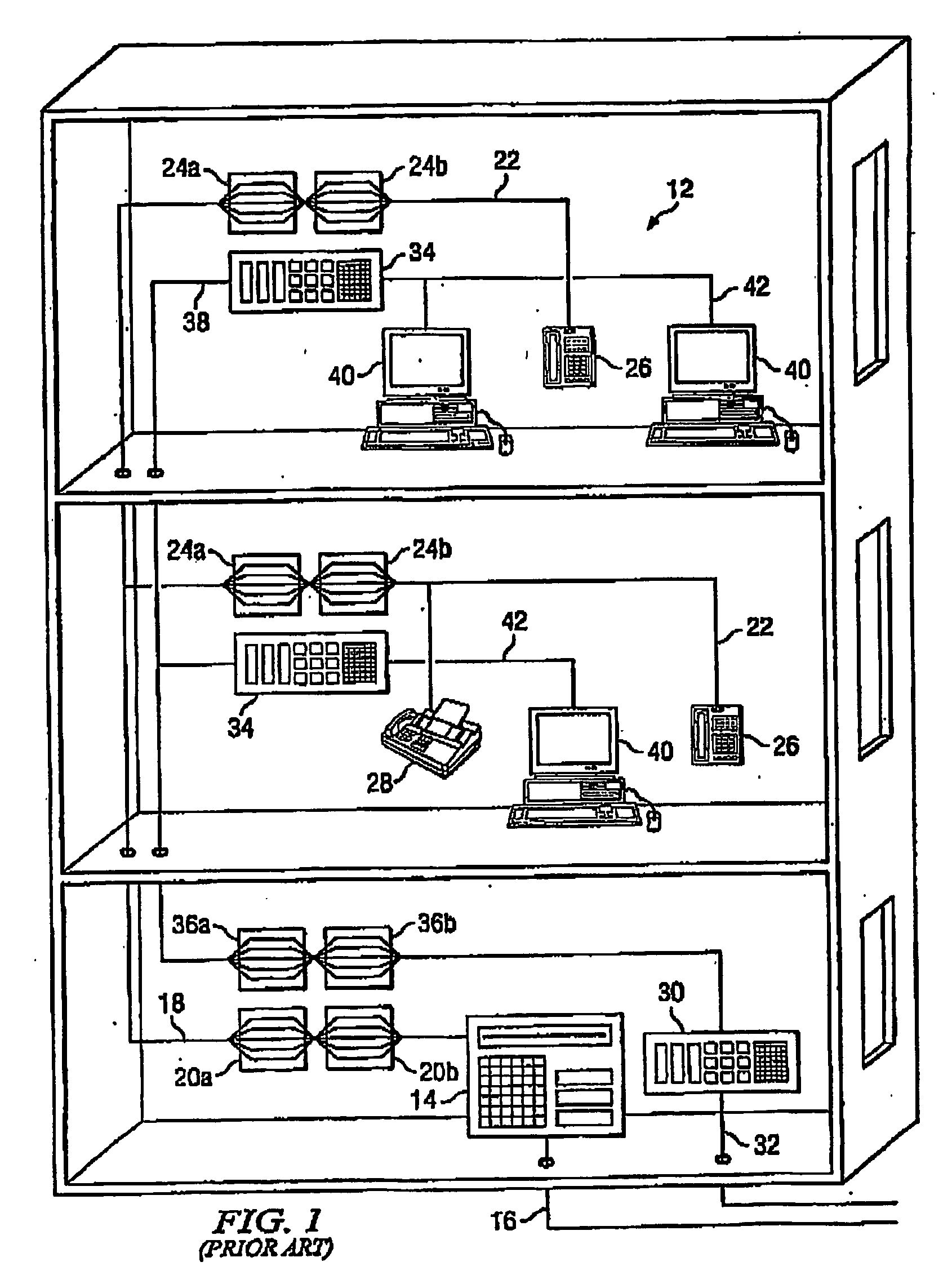
[0022]FIG. 1 is a art component diagram of a multi-story building wired with a standard prior art copper premises wiring system 12. The copper premises wiring system 12 includes a main telephone switch 14 that receives an incoming copper telecommunications cable 16 entering the building, thereby connecting the premises to a back-end telephone communications system. The telephone switch 14 is connected to a copper distribution cable 18 via a pair of patch panels 20a and 20b. Runs of copper cable 22 are connected to the copper distribution cable 18 via patch panels 24a, 24b and terminate at jacks (not shown) positioned throughout the building. Communications devices such as telephones 26 and facsimile machines 28 are connected to the jacks.
[0023] An active computer network component 30 such as a server also receives an incoming copper telecommunications cable 32 entering the building, thereby connecting the premises to a back-end data communications system. The active computer networ...
PUM
 Abstract
Description
Claims
Application Information