Process and Device for Obtaining Liquid Nitrogen by Low Temperature Air Fractionation

a technology of air fractionation and process, which is applied in the direction of refrigeration and liquifaction, lighting and heating apparatus, solidification, etc., can solve the problems of low separation efficiency, low efficiency of system, and high preliminary liquefaction of air introduced into the distillation column system, so as to achieve low energy consumption and use particularly efficiently

Inactive Publication Date: 2011-04-14
LINDE AG
View PDF10 Cites 1 Cited by
  • Summary
  • Abstract
  • Description
  • Claims
  • Application Information

AI Technical Summary

Benefits of technology

[0006]According to the present invention, a classical double column is replaced by two columns which both have a top condenser. An expanded throttle stream is introduced at least in part into the high-pressure column top condenser and there generates liquid nitrogen which can be applied as reflux to the high-pressure column and / or the low-pressure column and / or can be obtained directly as pressurized liquid product. In this manner, the cold contained in the throttle stream can be used particularly efficiently and a particularly low energy consumption results.

Problems solved by technology

A disadvantage of these known processes is the high preliminary liquefaction of the air introduced into the distillation column system.
This leads to a decreased separation efficiency and thereby to a relatively high energy consumption of the system.

Method used


Image

  • Process and Device for Obtaining Liquid Nitrogen by Low Temperature Air Fractionation
  • Process and Device for Obtaining Liquid Nitrogen by Low Temperature Air Fractionation
  • Process and Device for Obtaining Liquid Nitrogen by Low Temperature Air Fractionation

Examples


Embodiment Construction

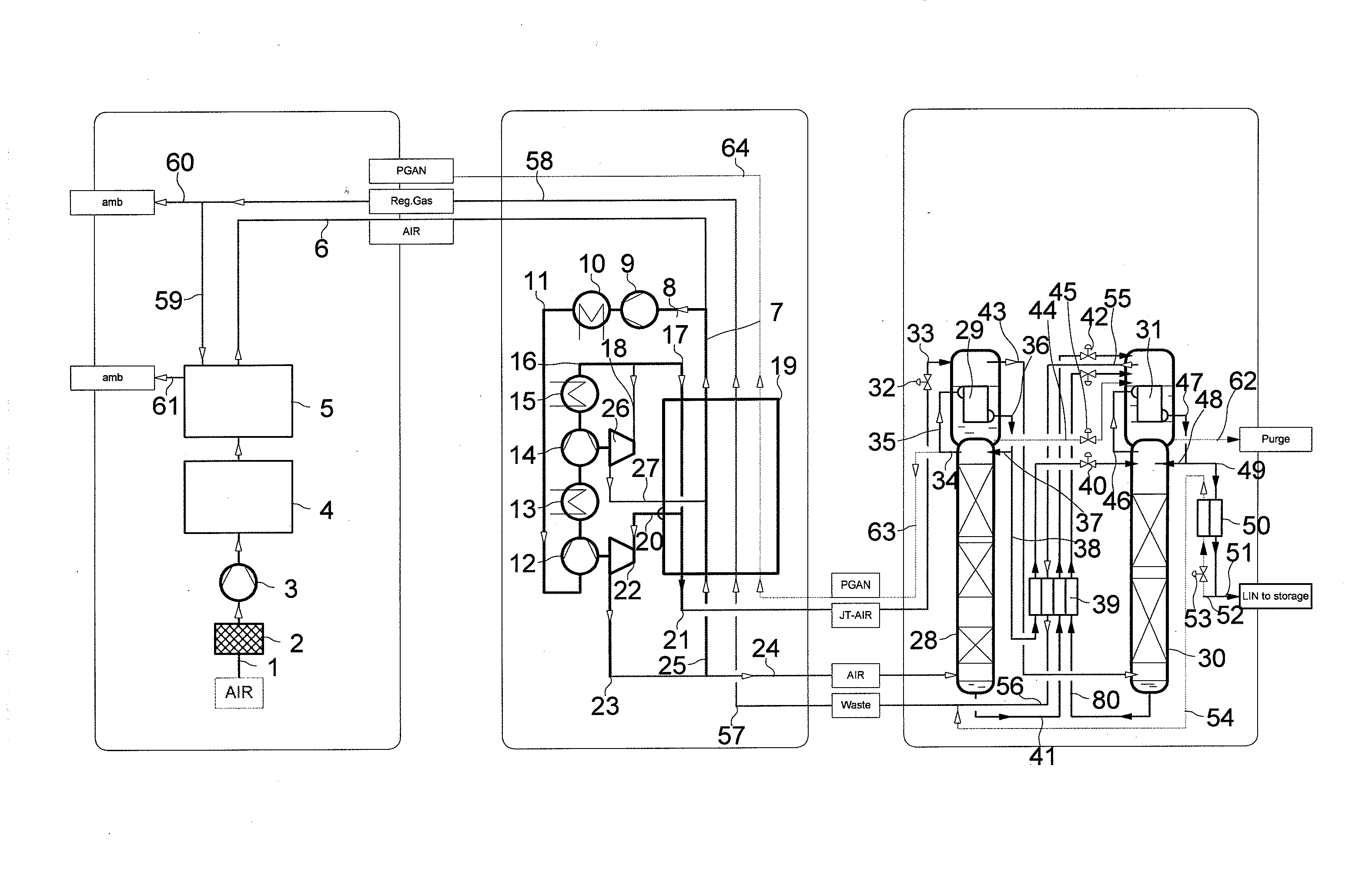
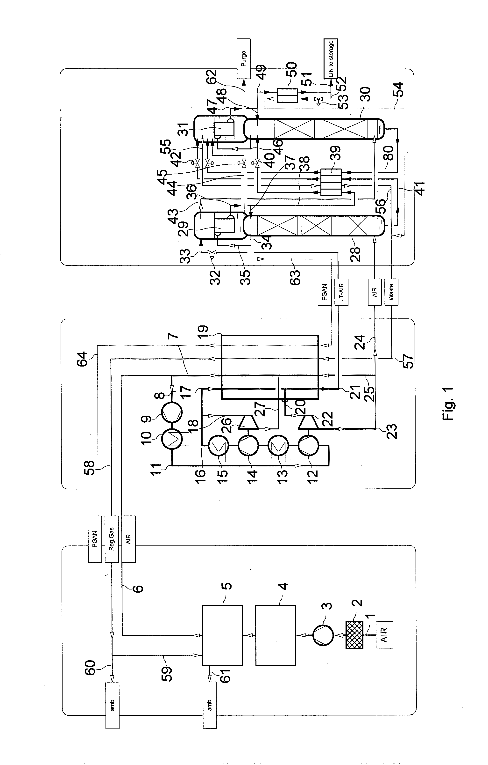
[0034]FIG. 1 is subdivided by three rectangles drawn in broken lines into the process parts pretreatment of air, cold system and distillation column system for nitrogen-oxygen separation (from left to right).

[0035]Incoming air 1 is fed via a filter 2 to a main air compressor 3 and compressed there to a first pressure of 5.5 to 7.0 bar and in a precooling appliance 4 is cooled back to about ambient temperature, for example, by indirect heat exchange in a heat exchanger or by direct heat exchange in a direct contact cooler.

[0036]The precooled air is purified at the first pressure in a purification appliance 5 which contains molecular sieve adsorbers. The purified air 6 (AIR) is fed to the cold system which serves for cooling the feed air and for generating liquefaction cold. There, the purified feed air 6 is first at least in part mixed with a return air stream 7 to give a circuit stream 8. The circuit stream 8 is further compressed to an intermediate pressure of 30 to 40 bar in a cir...


PUM


Abstract

A device for obtaining liquid nitrogen by low-temperature air fractionation in a distillation column system for nitrogen-oxygen separation includes a high-pressure column; a low-pressure column; a high-pressure column top condenser which is constructed as a condenser-evaporator and comprises a liquefaction compartment and an evaporation compartment; a low-pressure column top condenser which is constructed as a condenser-evaporator and comprises a liquefaction compartment and an evaporation compartment. A throttle stream is formed by one part of a purified feed air that is liquefied or pseudoliquefied in a main heat exchanger. The throttle stream is expanded, and at least some of the expanded throttle stream is introduced as refrigerant stream into the evaporation compartment of the high-pressure column top condenser.

Description

[0001]This U.S. patent application claims priority of European patent document 09012802.6 filed on Oct. 9, 2009, the entirety of which is incorporated herein by reference.FIELD OF INVENTION[0002]The present invention is directed to a process and device for obtaining liquid nitrogen by low-temperature air fractionation in a distillation column system.BACKGROUND OF INVENTION[0003]Liquid processes in which cold is transferred in a heat exchanger to a high-pressure air stream are known from EP 316768 A2 (FIG. 1); U.S. Pat. No. 5,660,059; or DE 102004046344. All of these processes comprise a conventional two-column system in which the high-pressure column top condenser (main condenser) is cooled by the bottoms liquid of the low-pressure column.[0004]A disadvantage of these known processes is the high preliminary liquefaction of the air introduced into the distillation column system. This leads to a decreased separation efficiency and thereby to a relatively high energy consumption of the...

Claims


Application Information

Patent Timeline
Patent Type & Authority Applications(United States)
IPC IPC(8): F25J3/04
CPCF25J3/042F25J3/0423F25J3/04278F25J3/04296F25J2270/90F25J3/04393F25J3/04424F25J2245/42F25J2270/02F25J3/04345F25J2200/20
Inventor ALEKSEEV, ALEXANDER
Owner LINDE AG
Why Eureka
Try Eureka