Eureka AIR delivers breakthrough ideas for toughest innovation challenges, trusted by R&D personnel around the world.

MRT film filter and plasma display apparatus having the same

a technology of which is applied in the field of microreplication technology (mrt) film filter and plasma display panel, can solve the problems of poor transparency, image distortion, and increase of the overall cost of the product, and achieve the effect of improving true contras

Inactive Publication Date: 2006-12-21
SAMSUNG SDI CO LTD
View PDF14 Cites 10 Cited by
  • Summary
  • Abstract
  • Description
  • Claims
  • Application Information

AI Technical Summary

Benefits of technology

The present invention provides a microreplication technology (MRT) film filter for a Plasma Display Panel (PDP) that can perform the functions of a strengthened glass filter film. The MRT film filter has improved interface characteristics to prevent dual images, reduced surface reflection, and improved true contrast. The MRT film filter includes a base film, an anti-glare layer, a conductive layer, an MRT film, and an adhesive. The base film is transparent, the anti-glare layer contains a hard coating material, the conductive layer can be made of at least one of ITO, Ag, Au, Cu, and Al, and the adhesive can contain a pigment or a dye for color correction or blocking neon light. The MRT film filter further includes a black coating on top of the MRT film to improve true contrast and a lens unit below the MRT film to focus visible light. The plasma display apparatus includes the MRT film filter.

Problems solved by technology

Such near infrared waves affect operations of, for example, wireless telephones or remote controls and cause malfunctions.
The mesh type front filter is excellent for blocking electromagnetic waves, but has relatively poor transparency and may cause distortion of an image.
Also, since the mesh itself is expensive, the overall cost of the product increases.
Therefore, the weight and cost of the plasma display apparatus are increased.
In addition, the conventional strengthened glass filter has a very complex structure in which films performing various functions are included.
Therefore, the manufacturing cost of the plasma display apparatus is increased.

Method used


Image

  • MRT film filter and plasma display apparatus having the same
  • MRT film filter and plasma display apparatus having the same
  • MRT film filter and plasma display apparatus having the same

Examples


Embodiment Construction

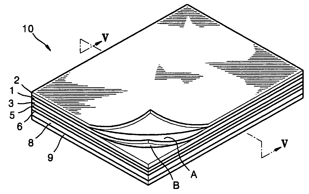
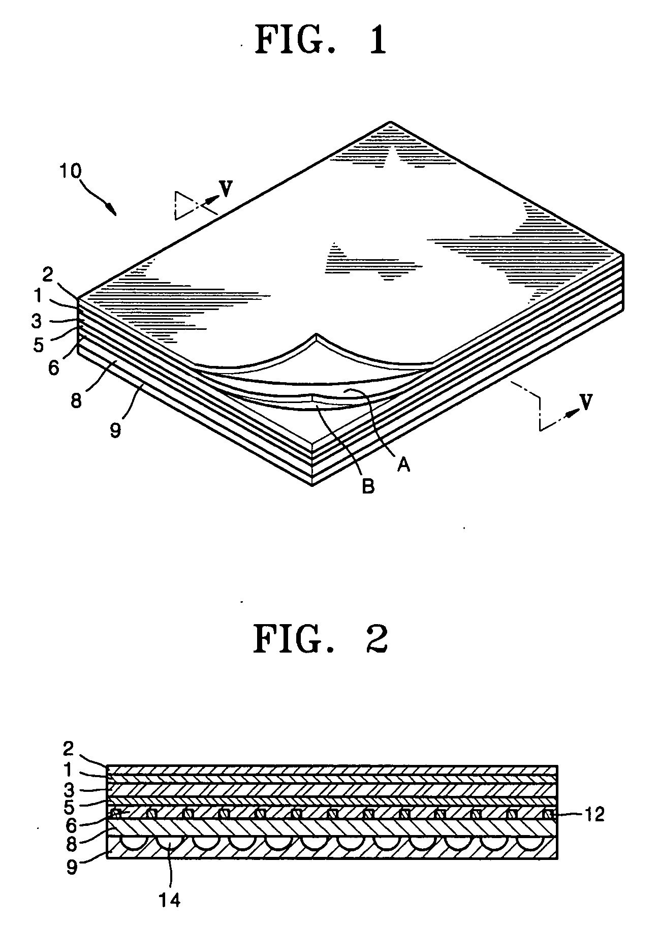
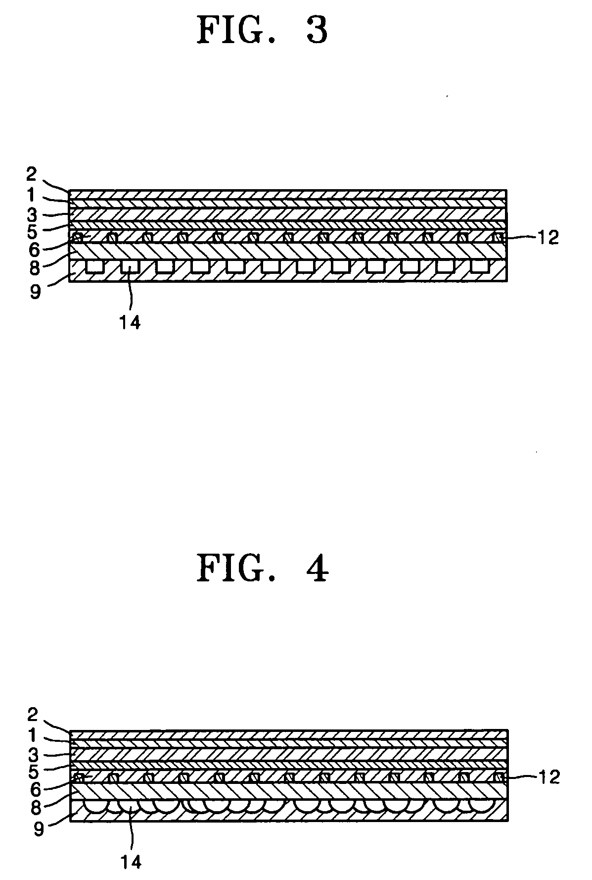
[0027]FIG. 1 is a perspective view of a microreplication technology (MRT) film filter 10 according to one embodiment. In FIG. 1, layers of the multi-layered MRT film filter are partially turned up so that the MRT film filter is clearly shown. FIG. 2 is a cross-sectional view of a portion of the MRT film filter 10 in FIG. 1 taken along line V-V.

[0028] Referring to FIGS. 1 and 2, the MRT film filter 10 includes a base film 3, an anti-glare layer 1, a hard coating material 2 preventing scratching, a conductive layer 5, an MRT film 8, which is a film made using a microreplication technique, and an adhesive 6 which fixes the base film 3 to the MRT film 8. The MRT film filter 10 may further include a supporter 9 which fixes the MRT film 8 to a flat display apparatus.

[0029] The flat display apparatus is a device which emits visible rays so that a viewer can see an image, and may be a device having a flat front surface through which the visible rays are emitted. Examples of the flat displ...


PUM

PropertyMeasurementUnit
visible transmittanceaaaaaaaaaa
thicknessaaaaaaaaaa
visible light transmittanceaaaaaaaaaa

Abstract

Provided is an MRT film filter that has improved interface characteristics, produces fewer dual images, and has reduced manufacturing costs. The MRT film filter includes: a base filter; an anti-glare layer disposed on top of the base film; a conductive layer that is disposed on one side of the base film and blocks electromagnetic waves; an MRT film disposed below the base film to be adhered to a flat display apparatus; and an adhesive adapted to fix the MRT film to the base film. Also provided is a plasma display device comprising the MRT film filter.

Description

CROSS-REFERENCE TO RELATED APPLICATIONS [0001] This application claims the priority of Korean Patent Application No. 10-2005-0051359, filed on Jun. 15, 2005, in the Korean Intellectual Property Office, the disclosure of which is incorporated herein in its entirety by reference. BACKGROUND OF THE INVENTION [0002] 1. Field of the Invention [0003] The present embodiments relate to a microreplication technology (MRT) film filter and a Plasma Display Panel (PDP), and more particularly, to an MRT film filter which is adhered directly to a front substrate of a flat display apparatus to block near infrared and electromagnetic waves and a plasma display apparatus having the same. [0004] 2. Description of the Related Art [0005] Strong near infrared waves are emitted in plasma display apparatuses due to the driving characteristics thereof. Such near infrared waves affect operations of, for example, wireless telephones or remote controls and cause malfunctions. [0006] In addition, plasma displa...

Claims


Application Information

Patent Timeline
Patent Type & Authority Applications(United States)
IPC IPC(8): B32B27/36B32B27/38B32B27/40B32B15/04B32B27/20B32B7/023G02B1/10G09F9/00H05K9/00
CPCB32B7/02H01J11/10Y10T428/265H01J2211/442H01J2211/446H01J11/44Y10T428/31678Y10T428/31786Y10T428/31511Y10T428/31507Y10T428/31504Y10T428/31663Y10T428/31971Y10T428/31721Y10T428/31551B32B7/023
Inventor KIM, JI-SUKLEE, SUNG-YONG
Owner SAMSUNG SDI CO LTD
Why Eureka
Eureka Blog
Learn More