Methods and devices for the suppression of harmonics

a harmonic and harmonic technology, applied in the field of radio frequency identification, can solve the problems of increasing the cost and complexity of the transponder, the antennae will not broadcast the transmitted signal efficiently, and the requirement of low q antennas of low efficiency

Inactive Publication Date: 2006-12-21
SATO HLDG CORP
View PDF20 Cites 37 Cited by
  • Summary
  • Abstract
  • Description
  • Claims
  • Application Information

AI Technical Summary

Benefits of technology

[0009] It is an object of the present invention, at least in some embodiments, to overcome or substantially ameliorate one or more of the deficiencies of the prior art or at least to provide a useful alternative.
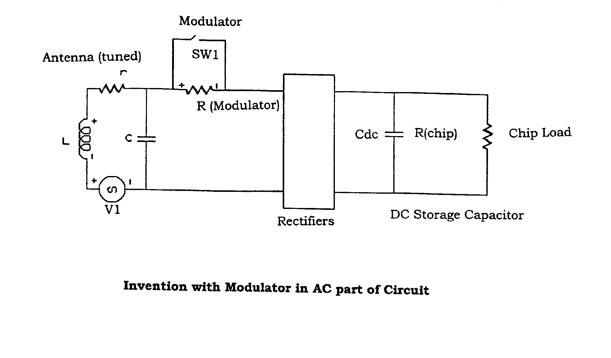
[0010] According to a first aspect of the present invention there is provided a method of suppressing harmonics of a signal transmitted from an antenna, the signal having a carrier with an imposed modulated data signal, the method comprising the steps of: providing a modulator associated with a controlled variable impedance, further providing the modulator in series with a load, the modulator being operable to modulate in accordance with the data signal, and being configured to produce a voltage across the antenna corresponding to a voltage provided by the controlled variable impedance.
[0011] According to a second aspect of the invention there is provided an antenna for suppressing harmonics of a signal transmitted from the antenna, the signal having a carrier with an imposed modulated data signal, the antenna including a modulator associated with a controlled variable impedance in series, the modulator being operable to modulate in accordance with the data signal, and being configured to produce a voltage across the antenna corresponding to a voltage provided by the controlled variable impedance.

Problems solved by technology

The need for separate antennae adds to the cost and complexity of the transponder.
Generally, these antennae are tuned to the received or interrogating frequency and, as such, the transmitted frequency can not differ greatly from the received frequency otherwise the antennae will not broadcast the transmitted signal efficiently.
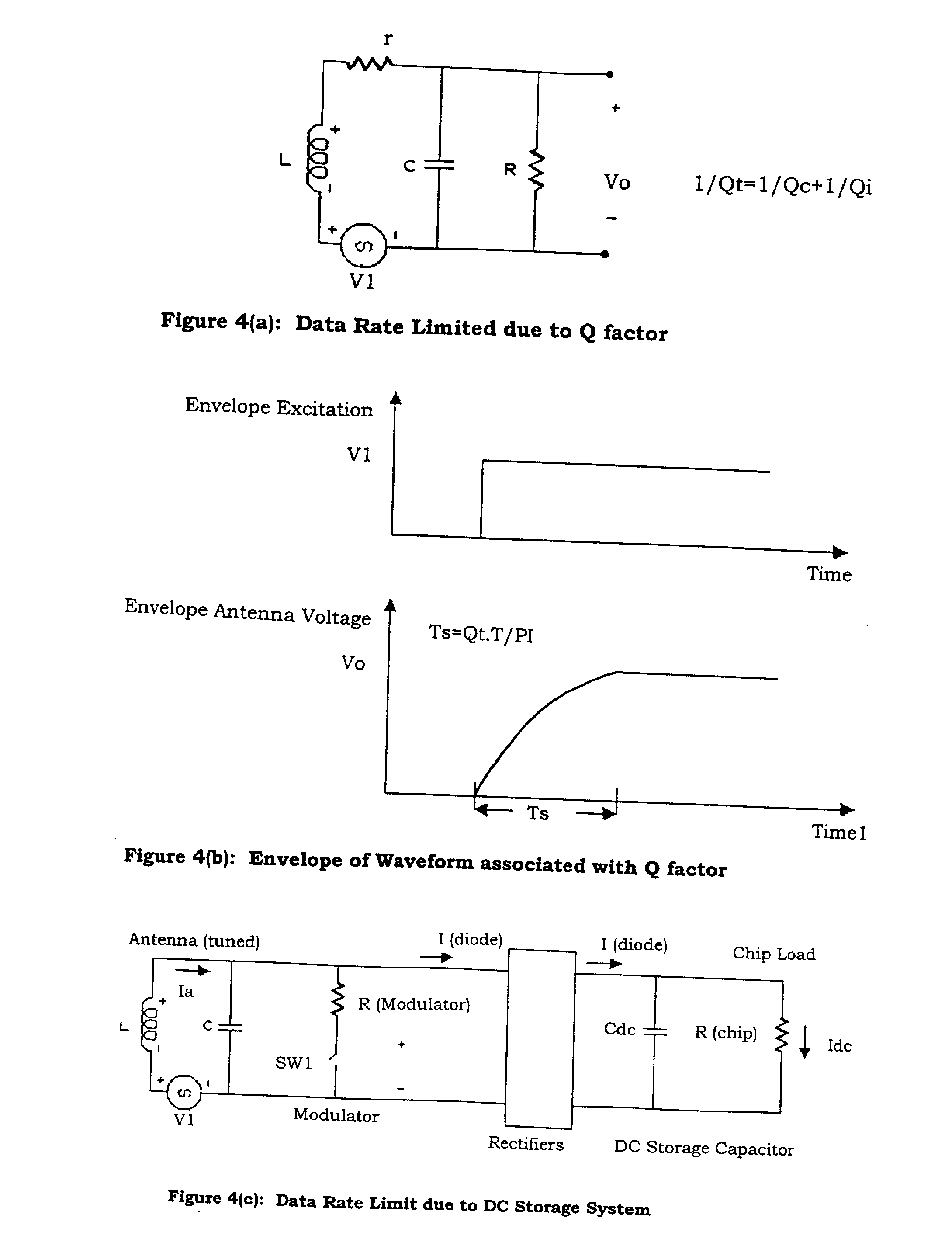
To transmit data at a high speed a low efficiency low Q antenna is required, however, to receive signals with high efficiency a high Q antenna is required.
This contradiction precludes the use of a high efficiency antenna for high speed data transmission.
The transmission efficiency of all these systems is degraded by this tuning arrangement and otherwise compromised by the stray capacitance of the antenna coil.
In addition to this problem LC filter arrangements cannot be readily incorporated into ASIC systems and present several difficulties.
Furthermore, in passive transponders the electrical inertia of the power storage system limits the data rate.

Method used


Image

  • Methods and devices for the suppression of harmonics
  • Methods and devices for the suppression of harmonics
  • Methods and devices for the suppression of harmonics

Examples


Embodiment Construction

[0048] In the following explanation of the invention there is description using both the time and frequency domain methods. It will be appreciated by those skilled in the art that the time domain methods provide information on the transient behaviour of various embodiments of the invention while the frequency domain methods are used to interpret the AC electrical behaviour. It will also be appreciated that the terms “transponder” and “transceiver” are used interchangeably.

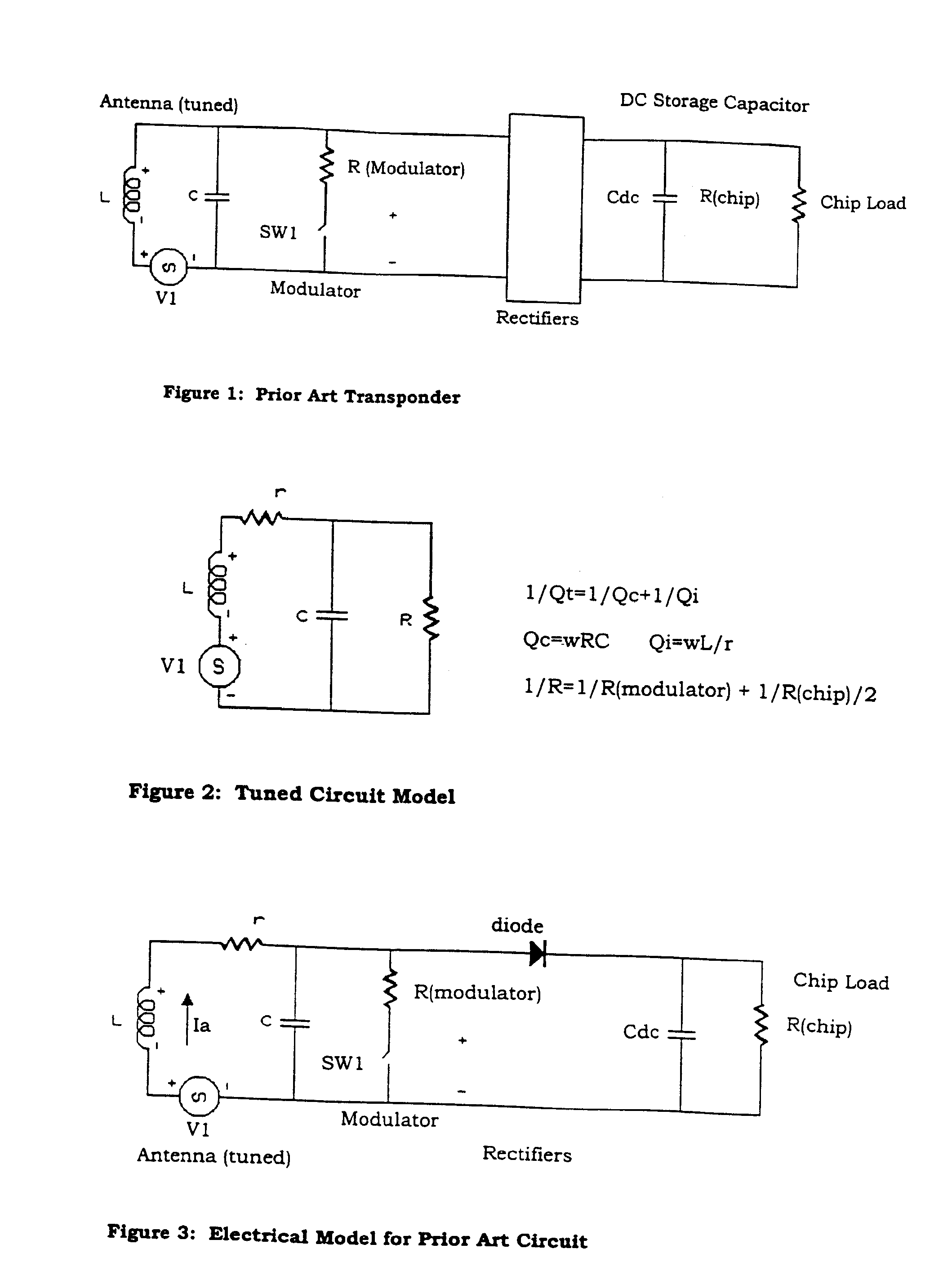
[0049] RFID transponders that incorporate a single antenna may be interrogated with an interrogating or exciting field. This field is received by the transponder's antenna and the voltage induced on the antenna may be rectified and used to power the transponder. It is necessary that the transponder be able to transmit messages back to its interrogator. For single antenna transponders the transmitted signal must be radiated off the same antenna that is used to receive the interrogating signal.

[0050] In prior art s...


PUM


Abstract

An antenna for suppressing harmonics of a signal transmitted from the antenna, the signal having a carrier with an imposed modulated data signal, the antenna including a modulator associated with a controlled variable impedance in series, the modulator being operable to modulate in accordance with the data signal, and being configured to produce a voltage across the antenna corresponding to a voltage provided by the controlled variable impedance.

Description

CROSS-REFERENCE TO RELATED APPLICATIONS [0001] This patent application is a continuation of U.S. patent application Ser. No. 09 / 601,122, filed as a national-stage application of International Patent Application No. PCT / AU99 / 00059, which was filed Jan. 29, 1999.TECHNICAL FIELD [0002] The invention has been developed primarily for the field of Radio Frequency Identification (RFID). Various embodiments will be described hereinafter with reference to that application. [0003] It will be appreciated, however that the invention is also applicable to other fields. More particularly, the invention is applicable to receiving and transmitting data to and from a transponder using a single antenna, where the transmission may occur at any number of distinct frequencies. The invention has particular merit when applied to passive transponders. That is, transponders which derive their operating power from the received excitation or interrogation signal. [0004] In arrangements the present invention p...

Claims


Application Information

Patent Timeline
Patent Type & Authority Applications(United States)
IPC IPC(8): H04B1/38G01S13/74G01S13/75G01S13/76G01S13/79G06K7/00G06K19/07G06K19/077H04B1/59
CPCG01S13/74G01S13/75G06K7/0008G06K19/07777G06K19/07749G06K19/07758G06K19/0723
Inventor MURDOCH, GRAHAM ALEXANDER MUNRO
Owner SATO HLDG CORP
Why Eureka
Try Eureka