Reactive capacitance compensation cabinet

A technology of capacitor compensation cabinet and compensation unit, which is applied in reactive power compensation, reactive power adjustment/elimination/compensation, cooling/ventilation of substation/switchgear, etc., and can solve the problem of single compensation and inadequate compensation of reactive capacitor compensation cabinet Can not achieve the effect, the service life of the capacitor is short, etc., to achieve the effect of reducing and suppressing harmonics, reducing loss, and improving power factor

Inactive Publication Date: 2013-03-20
张家港保税区天翔电气有限公司
View PDF9 Cites 18 Cited by
  • Summary
  • Abstract
  • Description
  • Claims
  • Application Information

AI Technical Summary

Problems solved by technology

[0002] At present, enterprises consume a lot of electricity and have high requirements, and there are more and more inductive devices in the terminal power consumption equipment. The original reactive capacitor compensation cabinet has a single compensation and can only compensate for three phases; the response time is slow, and the response is second-level; The electrical components of the main circuit are AC contactor + capacitor, the three-phase imbalance, the grid harmonics cause the service life of the capacitor to be short, or the capacitor capacity that needs to be switched is adjusted accordingly due to frequent changes in the terminal load capacity, and the compensation is not in place. No effect, and overcompensation has a negative impact on the entire grid

Method used


Image

  • Reactive capacitance compensation cabinet
  • Reactive capacitance compensation cabinet
  • Reactive capacitance compensation cabinet

Examples


Embodiment Construction

[0017] The present invention will be described in further detail below through specific examples.

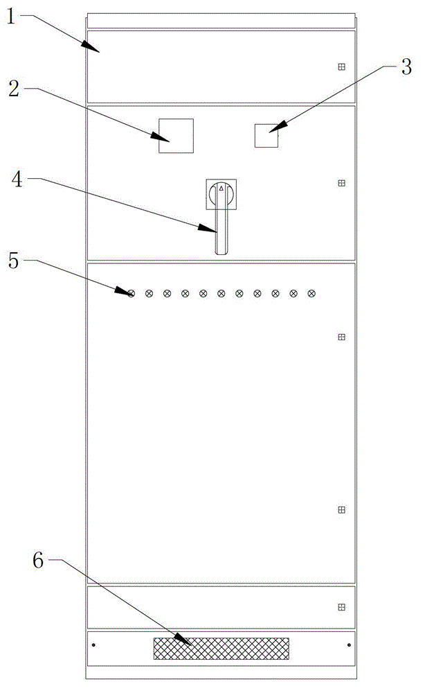
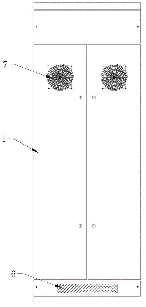
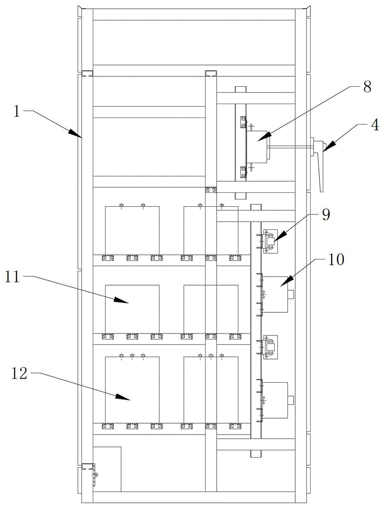
[0018] Such as Figure 1 to Figure 4 As shown, a reactive capacitance compensation cabinet includes a cabinet body 1, and various electrical components are installed in the cabinet body 1, because the electrical components in the cabinet body 1 will generate heat during operation, therefore, the cabinet body 1 Equipped with cooling device. The heat dissipation device includes a ventilation grid hole 6 arranged at the bottom of the cabinet body 1 and a cooling fan 7 arranged at the upper end of the cabinet body 1. The ventilation grid hole 6 is arranged on the front panel and the rear panel of the cabinet body 1, and the cooling fan 7 Then it is arranged on the rear panel of the cabinet body 1 . When the heat dissipation fan 7 is started, the heat in the cabinet body 1 is taken away, and the low-temperature air enters the cabinet body 1 from the ventilation grid hole 6, thereby...


PUM


Abstract

The invention discloses a reactive capacitance compensation cabinet which comprises a cabinet body, wherein the cabinet body is internally provided with a plurality of three-phase compensation units, a plurality of split phase compensation units, a breaker and a controller; each the three-phase compensation unit comprises three compensation single-phase circuits; the compensation single-phase circuits comprise fuses, reactors, switching switches and capacitors that are electrically connected sequentially; the three compensation single-phase circuits adopt delta connection; each split phase compensation unit comprises three split compensation single-phase circuits; the three split compensation single-phase circuits adopt star connection; the three-phase compensation units and the split phase compensation units are connected with an outside three-phrase power grid by the breaker; the switching switches are connected with the controller; and the controller is connected with a detection unit for detecting current signals and voltage signals of the three-phrase power grid. The compensation cabinet combines three-phase compensation and split phase compensation, and can conduct intelligent switching conversion and automatic combined configuration, and inhibit and filter harmonic waves.

Description

technical field [0001] The invention relates to a reactive capacitance compensation cabinet, which can be used in conjunction with a low-voltage power distribution cabinet. Background technique [0002] At present, enterprises consume a lot of electricity and have high requirements, and there are more and more inductive devices in the terminal power consumption equipment. The original reactive capacitor compensation cabinet has a single compensation and can only compensate for three phases; the response time is slow, and the response is second-level; The electrical components of the main circuit are AC contactor + capacitor, the three-phase imbalance, the grid harmonics cause the service life of the capacitor to be short, or the capacitor capacity that needs to be switched is adjusted accordingly due to frequent changes in the terminal load capacity, and the compensation is not in place. There is no effect, and overcompensation has a negative impact on the entire grid. Con...

Claims


Application Information

Patent Timeline
Patent Type & Authority Applications(China)
IPC IPC(8): H02J3/18H02J3/01H02B1/56H02B1/04
CPCY02E40/30Y02E40/40
Inventor 袁龙武
Owner 张家港保税区天翔电气有限公司
Why Eureka
Try Eureka