Asymmetric connecting wire balancing transformer and implementation method thereof

A technology for balancing transformers and implementation methods, which is applied in the directions of transformer/inductor cores, transformer/inductor coils/windings/connections, etc., and can solve problems such as complex structures of windings and iron cores, difficulties in production and implementation, and increased costs

Inactive Publication Date: 2012-05-30
HUNAN UNIV +2
View PDF5 Cites 0 Cited by
  • Summary
  • Abstract
  • Description
  • Claims
  • Application Information

AI Technical Summary

Problems solved by technology

[0004] 1) The high-voltage side of the Scott connection transformer cannot lead to the neutral grounding point, and the utilization rate of materials is not high. Since the high-voltage and low-voltage sides of the transformer do not have a triangular circuit, the magnetic flux and voltage contain third harmonic components, which affect the voltage waveform and affect the communication along the line. bring disturbance
When Scott wiring is used for AT connection, the two-phase side needs to be designed according to 55KV, which increases the cost
In addition, the winding and core structures are complex;
[0005] 2) The primary side of the LeBlanc connection transformer is connected in a triangle, which eliminates the influence of the third harmonic flux, but there is no neutral point on the high-voltage side, and it needs to be designed according to full insulation, which increases the cost. When used for AT power supply, due to the two-phase There is no common point, and two autotransformers with half the capacity of the main transformer need to be added, which increases the overall investment
[0006] 3) For Woodbridge wiring, the neutral point of the high-voltage side can be directly grounded, and the high-voltage winding can be designed according to the graded insulation (phase voltage). There is a triangular circuit on the low-voltage side, but the two-phase outgoing line on the low-voltage side has no common point, so two sets are required. Autotransformer (AT), which greatly increases equipment investment
[0008] It is worth noting that the existing three-phase to two-phase balance transformers require the secondary side winding to be two-phase or three-phase winding symmetrical (the symmetry mentioned in this paper refers to the number of winding turns, impedance and layout form are the same), this It brings difficulty to production implementation, and in actual operation, especially when the winding is short-circuited, it is deformed by a large electromotive force. In fact, it is difficult to ensure symmetry in production and operation, so the final application performance of the product is greatly affected. big impact

Method used


Image

  • Asymmetric connecting wire balancing transformer and implementation method thereof
  • Asymmetric connecting wire balancing transformer and implementation method thereof
  • Asymmetric connecting wire balancing transformer and implementation method thereof

Examples


Embodiment 1

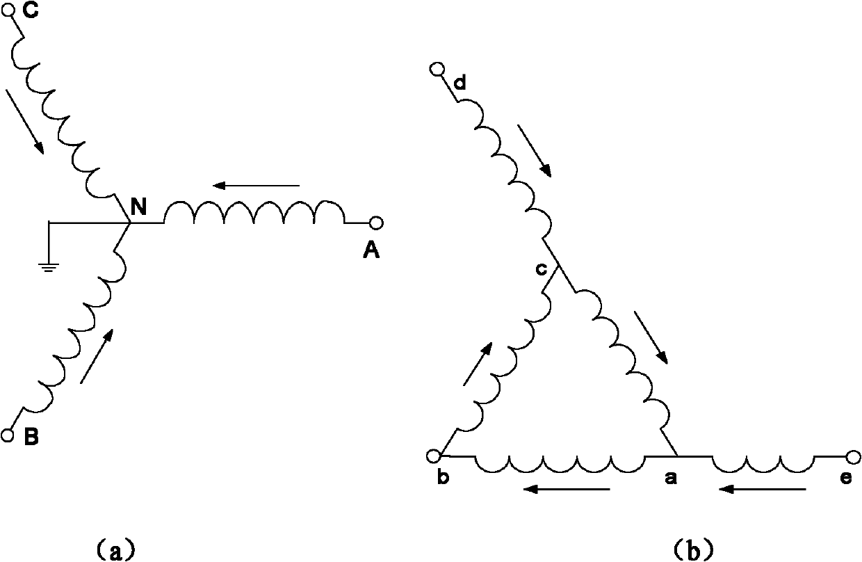
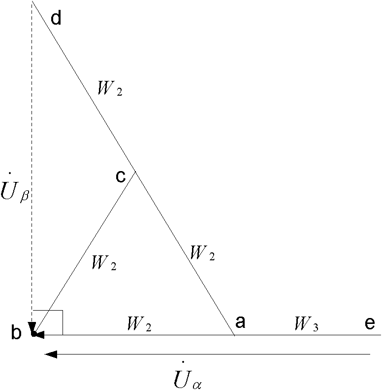
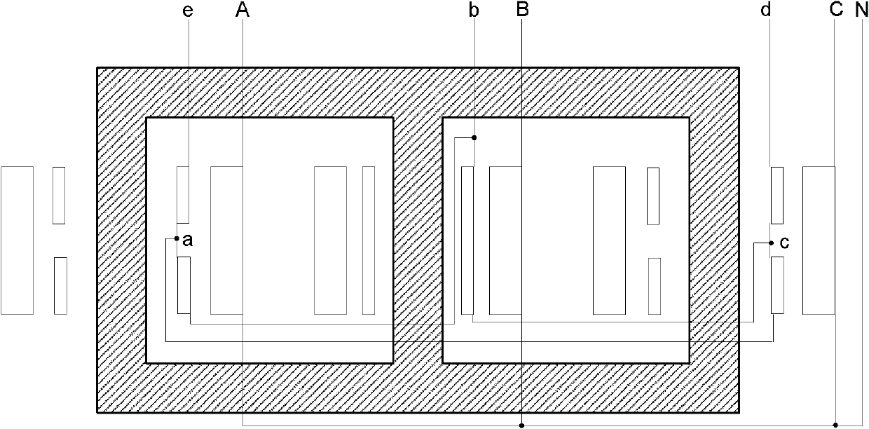
[0065] exist figure 1 Among them, the primary side winding is composed of three-phase windings AN, BN and CN, and is connected in star shape; the secondary side winding is composed of A-phase winding ab and ea, B-phase winding bc, and C-phase winding ca and dc. Among them, ab, bc, and ca are connected to form a closed triangle, forming the path of the third harmonic current. The primary sides A, B and C form a three-phase system, and the neutral point N is allowed to be grounded; the secondary sides e, b, d, and b form a two-phase system, which can supply power simultaneously or separately; [single-phase power supply directly at e, Point b is connected to the resistive charge; for two-phase power supply, points d and b are also connected to the load at the same time. Point b is a public point, not a grounding point. 】The number of turns of the three-phase winding on the primary side is W 1 , the number of turns of the secondary side windings ab, bc, ca and dc are all W 2 ,...

Embodiment 2

[0081] If the secondary side winding is connected to the top, the middle point is point o. Then a symmetrical two-phase system can be obtained from a1, c1 and b1, d1. A symmetrical four-phase system can also be obtained from a1o, b1o, c1o and d1o.

[0082] see Figure 5 and Figure 6 , The neutral point of the primary side is allowed to be grounded, and the secondary side is derived from a1, c1, b1, and d1, which have two phases of equal size and 90° phase difference. Symmetrical voltage constitutes a two-phase system. At the same time, four-phase symmetrical voltages can be obtained from a1o, b1o, c1o and d1o, realizing the function of changing three phases to four phases.

[0083] Figure 9 This is the three-phase current waveform diagram of the primary side when the four-phase side of the wiring is equipped with a balanced load. Figure 9 .a indicates that the three-phase current waveform is uniform and is a symmetrical three-phase waveform, Figure 9 .b and Figure ...


PUM


Abstract

The invention discloses an asymmetric connecting wire balancing transformer and an implementation method thereof. The transformer comprises an iron core, a primary side winding and a secondary side winding, and is characterized in that: the primary side winding adopts a Y-shaped connecting wire; a neural point N of the Y-shaped connecting wire is grounded; the number of circles of the primary side winding is W1; in the secondary side winding, the A-phase winding consists of two windings, namely ea and ab; the B-phase winding consists of one winding bc; and the C-phase winding consists of two windings, namely dc and ca; the number of circles of the windings ab, bc, ca and dc is W2, and the number of circles of the winding ea is W3; the windings ab, ca and ea are connected with one another at a point a serving as a common point, the windings ca, bc and dc are connected with one another at a point c serving as another common point, and the windings ab and bc are connected with each otherat a point b serving as another common point; two no-load voltages Ueb and Udb are equal to each other; and the phase difference is 90 degrees. The secondary side of the asymmetric connecting wire balancing transformer has an asymmetric winding structure, so the production is convenient to execute, the comprehensive performance is high, the structure is simple, and the material utilization rate is high.

Description

technical field [0001] The invention belongs to the field of power transformers, and relates to an asymmetric connection balance transformer and a realization method thereof, which are applied in fields such as electrified railways or industrial frequency electric furnaces. Background technique [0002] The traditional power transmission and distribution system is a three-phase system, but many users need two-phase or single-phase power supply, which will inevitably cause asymmetric operation of the three-phase system, resulting in large negative-sequence current and zero-sequence current components, so that the power grid The quality of power supply deteriorates, affecting the normal power supply of other users. In the traction network of electrified railways, since two-phase power is also used, its asymmetrical operation is particularly serious. For the three-phase power grid of 110KV and above, the high voltage side of the transformer generally adopts the neutral point g...

Claims


Application Information

Patent Timeline
Patent Type & Authority Patents(China)
IPC IPC(8): H01F27/28H01F27/24
Inventor 罗隆福许志伟张志文许加柱
Owner HUNAN UNIV
Why Eureka
Try Eureka