Mechanical energy storage highway deceleration band power generation device

A technology for mechanical energy storage and power generation devices, applied in mechanical equipment, machines/engines, mechanisms that generate mechanical power, etc. The effect of recycling, simple and clear structure

Active Publication Date: 2020-09-08
WUHAN UNIV
View PDF7 Cites 0 Cited by
  • Summary
  • Abstract
  • Description
  • Claims
  • Application Information

AI Technical Summary

Problems solved by technology

In summary, the current similar speed reduction belt power generation device mainly has the following disadvantages: (1) The mechanism is too complicated, such as setting speed regulating valves, check valves, electromagnetic reversing valves and other valves in a set of devices, using hydraulic motors Devices with too complicated components
(2) The production cost of the device is high and it is not easy to maintain
(3) Easily damaged and difficult to repair
(4) The energy output is unstable, which is not conducive to power generation
(5) The deformation required for the components used to collect the deformation is relatively large, which either cannot meet the requirements in real life, or the corresponding deformation will cause the vehicle to be interrupted, so the practicability is poor
(6) The reversing device used has a large radius of gyration and takes up a lot of volume, which violates the requirement for a simplified structure of the deceleration belt

Method used


Image

  • Mechanical energy storage highway deceleration band power generation device
  • Mechanical energy storage highway deceleration band power generation device
  • Mechanical energy storage highway deceleration band power generation device

Examples


Embodiment Construction

[0026] The present invention will be further described in detail below in conjunction with the accompanying drawings and specific embodiments.

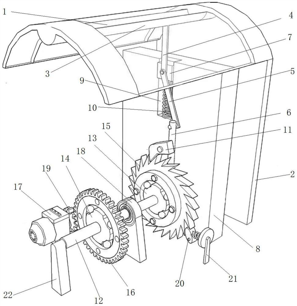
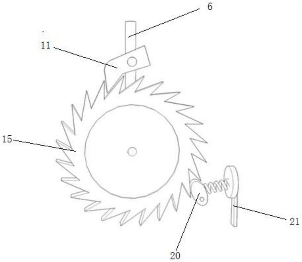
[0027] The invention is a mechanical energy storage type road deceleration belt power generation device, such as Figure 1-5 As shown, the present invention includes a mechanical transmission part and an energy storage power generation part;

[0028] The mechanical transmission part includes a deceleration belt 1 fixed on the road, a support frame 2 arranged on the side of the deceleration belt, a metal strip 3 fixed on the lower surface of the deceleration belt, a first crank 4 hinged on the metal strip 3, the first A crank 4, a second crank 5, and an active swing rod 6 are hinged sequentially. The first crank 4 and the second crank 5 are jointly hinged on the slider 7. A support plate 8 is provided inside the speed reduction belt box. On the support plate 8 There is a guide groove 9, the slider 7 is installed in the guide groove 9 ...


PUM


Abstract

The invention discloses a mechanical energy storage type highway speed bump power generation device comprising a mechanical transmission part and an energy storage power generation part. The mechanical transmission part mainly comprises a speed bump, a supporting frame, a metal strip, a first crank, a second crank and a driving swing rod, wherein the first crank, the second crank and the driving swing rod are sequentially hinged; one end of the first crank is hinged to the metal strip, the other end of the first crank and the second crank are jointly hinged to a sliding block, the sliding block is mounted in a guiding groove in a supporting plate, and a return spring is mounted on the lower portion of the sliding block in the guiding groove; a driving pawl of a ratchet wheel structure andthe driving swing rod are fixed, a rotating shaft is fixedly connected with a first one-way clutch and a second one-way clutch which are opposite in linkage direction, and the outer circle of the first one-way clutch is fixedly connected with a ratchet wheel; the energy storage power generation part comprises a power generator and a spring-type elastic energy storage device, a mounting gear is arranged on a power generator shaft, and the mounting gear is engaged with an external gear at the outer circle of the second one-way clutch. According to the mechanical energy storage type highway speedbump power generation device, the multistage variable speed is set, the high transmission ratio is achieved as much as possible through the smallest space, mounting is convenient, and the power generation amount is large.

Description

technical field [0001] The invention relates to the technical field of power generation devices, in particular to a mechanical energy storage type road deceleration belt power generation device. Background technique [0002] At present, in order to limit the speed of vehicles and ensure driving safety, road speed bumps are installed on many roads. When the vehicle passes the deceleration belt, it will produce a huge impact, which will bring discomfort to the passengers and lose part of the energy. If the power generating device of the present invention can be installed on the road deceleration belt, the energy can be recovered and utilized, and the ride comfort can be improved, bringing certain social and economic value. [0003] Considering the particularity of the installation location of the road speed bump device, it is difficult to replace it frequently once it is installed. The designed device should not be easily damaged and have a long service life. In addition, if ...

Claims


Application Information

Patent Timeline
Patent Type & Authority Patents(China)
IPC IPC(8): F03G7/00F03G1/00
CPCF03G1/00F03G7/00
Inventor 刘洋万紫琼雷舒婷周静颖李琦徐彤
Owner WUHAN UNIV
Why Eureka
Try Eureka