Stacked microvias and method of manufacturing same

a microvia and stacked technology, applied in the direction of printed circuit aspects, semiconductor/solid-state device details, printed element electric connection formation, etc., can solve the problems of copper failure, affecting the reliability of microvias, and increasing the processing capability of circuitry

Inactive Publication Date: 2006-12-28
INTEL CORP
View PDF5 Cites 43 Cited by
  • Summary
  • Abstract
  • Description
  • Claims
  • Application Information

AI Technical Summary

Problems solved by technology

This demand presents an acute challenge to retain and advance the integrity of the prior-generation electronic component packages while dramatically increasing the processing capability of the circuitry.
Therefore, the effect of the proximity of microvias to plated through holes (PTH

Method used


Image

  • Stacked microvias and method of manufacturing same
  • Stacked microvias and method of manufacturing same
  • Stacked microvias and method of manufacturing same

Examples


Embodiment Construction

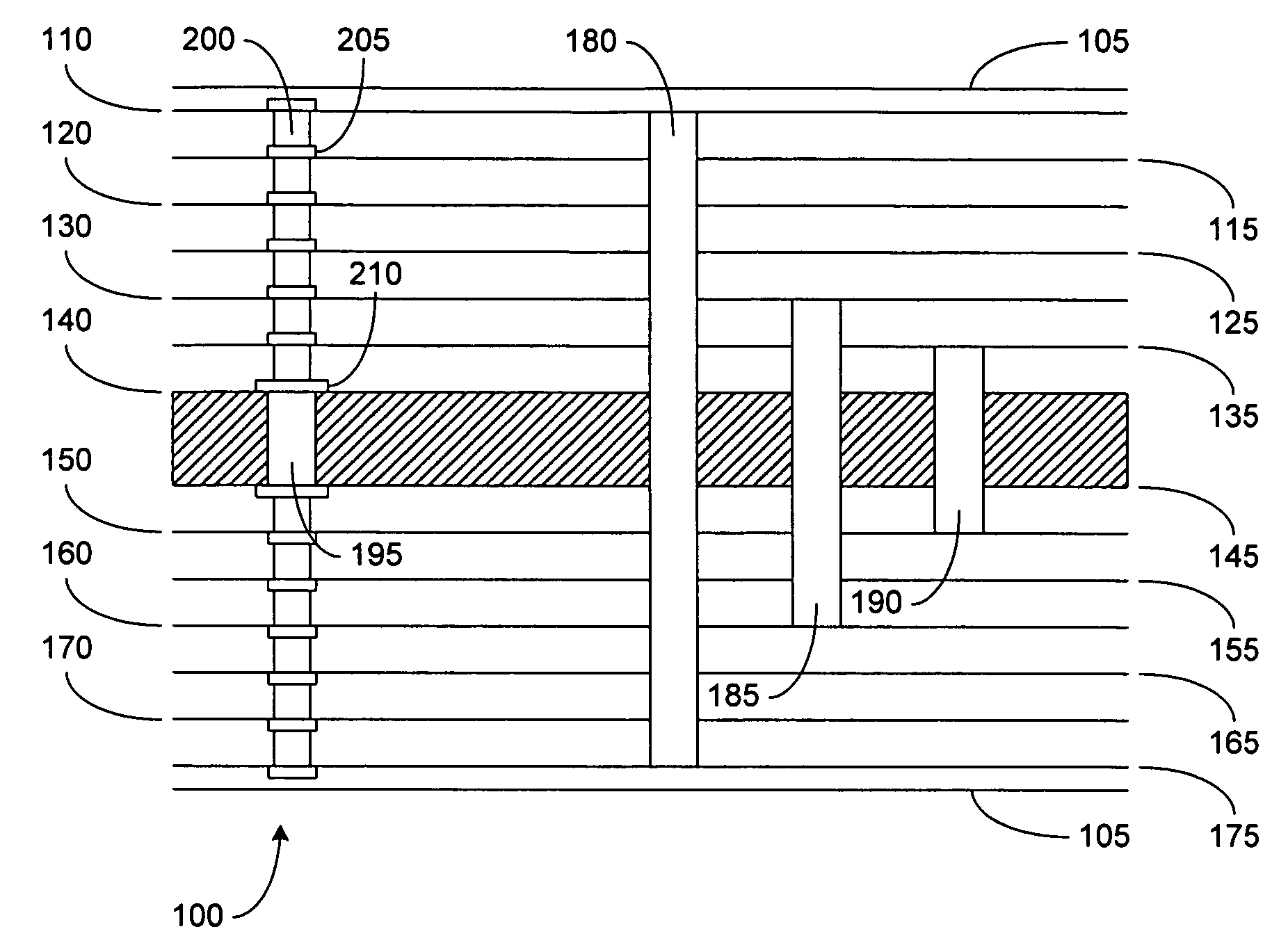
[0013] In the following description and claims, the terms “connected” and “coupled,” along with their derivatives, may be used. It should be understood that these terms are not intended as synonyms for each other. Rather, in particular embodiments, “connected” may be used to indicate that two or more elements are in direct physical or electrical contact with each other. In contrast, “coupled” may mean that two or more elements are in direct physical or electrical contact with each other or that the two or more elements are not in direct contact but still cooperate or interact with each other.

[0014]FIG. 1 depicts a multi-layer printed circuit board (PCB) 100 in which embodiments of the present invention may be implemented. In general, electronic component packages such as PCB 100 may be manufactured using conductive traces on the surface 105, or X-Y plane, of the electrical circuit's substrate to connect discrete electronic devices. Distinct layers 110, 115, 120, 125, 130, 135, 140,...


PUM

PropertyMeasurementUnit
Diameteraaaaaaaaaa

Abstract

A flip chip package may include stacked vias in which the diameter D1 of the outermost via is less than the diameter D2 of the innermost via. The ratio D2/D1, for example, may be 1.5 to 2.

Description

BACKGROUND OF THE INVENTION [0001] Embodiments of the present invention relate generally to flip chip and chip scale technologies for creating single chip or multi-chip modules (MCM), integrated circuit (IC) cards, memory cards, very dense surface mount assemblies, and the like. [0002] More particularly, embodiments of the invention relate to stacked vias and methods of manufacturing same for use in chip scale packaging variations, which include but are not limited to flip chip packages, high density interconnect (HDI) packages, micro ball grid array (μBGA) packages, micro surface mount technology (MSMT) packages, and slightly larger than integrated circuit carriers (SLICC) packages. [0003] With changes in sophistication of electronic equipment over the years, manufacturers of electronic component packages have produced higher density circuits in smaller packages. High interconnect density on electronic component packages is provided by utilizing multi-layer circuits separated by a ...

Claims


Application Information

Patent Timeline
IPC IPC(8): H05K1/11H05K3/42
CPCH01L23/49827H01L23/49838H05K1/112H05K1/115H05K3/4602Y10T29/49165H05K2201/096H01L2924/0002H05K2201/0352H01L2924/00
Inventor TAKEUCHI, TIMOTHY M.SRINTVASAN, SRIRAMSANF, SANDEEP B.
Owner INTEL CORP
Why Eureka
Try Eureka